background image


V1.1_20110816 


USER MANUAL 


AWRT-150 

150Mbps Wireless ADSL2+ Router


Summary of Contents for AWRT-150

Page 1: ...V1 1_20110816 USER MANUAL AWRT 150 150Mbps Wireless ADSL2 Router ...

Page 2: ...the equipment into an outlet on a circuit different from that to which the receiver is connected Consult the dealer or an experienced radio TV technician for help To assure continued compliance any changes or modifications not expressly approved by the party responsible for compliance could void the user s authority to operate this equipment Example use only shielded interface cables when connecti...

Page 3: ...ng a thunderstorm should be avoided Do not place heavy objects on the casing RECYCLING NOTICE The symbol of the crossed out wheeled bin on this product means that it is forbidden to place the equipment waste together with other waste under penalty of fine Detailed information about recycling of the product can be obtained at local authorities local waste treatment plants or local distributors Forw...

Page 4: ...150Mbps Wireless ADSL2 Router User Manual 4 ...

Page 5: ...o 10 mW e i r p within the band 2454 2483 5 MHz Military Radiolocation use Refarming of the 2 4 GHz band has been ongoing in recent years to allow current relaxed regulation Full implementation planned 2012 Italy none If used outside of own premises general authorization is required Luxembourg none General authorization required for network and service supply not for spectrum Norway Implemented Th...

Page 6: ...er adapter 2x RJ 11 Telephone cable Ethernet cable External splitter Quick Installation Guide CD Rom Make sure that the package contains above items If any of the above items is missing or damaged please contact the store you bought this product from Manufactured for Sunnyline Computer Products Poland Sp z o o ul Graniczna 58 B 62 082 Przeźmierowo POLAND ...

Page 7: ...dows Vista as below 17 3 2 Login 20 4 Modem Management 22 4 1 Convenient Setup 22 4 2 Internet Setup 24 4 2 1 Internet Setup 25 4 2 2 QoS for PVC 26 4 2 3 ADSL Setup 28 4 2 4 Port Mapping 29 4 3 System Information 30 4 4 System Log 31 4 5 Wireless Management 32 4 5 1 Basic 32 4 5 2 Security 33 4 5 3 Host Filter 35 4 5 4 Host List 36 4 5 5 WPS 36 4 5 6 Advanced 37 4 6 Security Setup 38 4 6 1 MAC Fi...

Page 8: ...12 2 Remote Access 51 4 12 3 TR 069 Configuration 51 4 13 System Management 53 4 13 1 Password Setup 53 4 13 2 Upgrade 53 4 13 3 Reboot 53 4 13 4 Backup 54 4 13 5 Restore 54 4 13 6 WOL Wake up On LAN 54 4 13 7 System Time 55 5 Appendix 56 5 1 Wireless Network 56 5 2 FAQ 60 5 2 1 How to restore the default parameter of the modem 60 5 2 2 How to upgrade the modem 61 5 2 3 How to connect the modem af...

Page 9: ...t of the Web based Utility is supplied and friendly help messages are provided for the configuration Network and Router management is done through the Web based Utility which can be accessed through local Ethernet using any web browser ADSL 8level AWRT 150 supports full rate ADSL2 connectivity conforming to the ITU and ANSI specifications In addition to the basic DMT physical layer functions the A...

Page 10: ...et when idle Provides reliable ESD and surge protect function with quick response semi conductive surge protection circuit High speed and asymmetrical data transmit mode provides safe and exclusive bandwidth Supports All ADSL industrial standards Provides integrated access of internet and route function which face to SOHO user Built in DHCP server Built in firewall supporting MAC filter IP filter ...

Page 11: ...r AWRT 150 without any explanations Parameters provided in the pictures are just references for setting up the product which may differ from the actual situation 1 4 Working Environment Temperature 0 to 40 C operating 40 to 70 C storage Humidity 10 to 90 non condensing operating 5 to 90 non condensing storage Power DC 5V ...

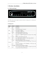
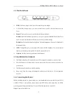
Page 12: ... PPP connection has been built Off There is no successful PPP connection or the Router works on Bridge mode WLAN Flash There is wireless data being transmitted On The wireless function is enabled but no data is being transmitted Off The wireless function is disabled LAN 1 4 Flash Data is being transferred over the 1 4 LAN port On There is a successful connection on the corresponding 1 4 LAN port b...

Page 13: ...Or you can connect them by an external separate splitter For details please refer to 2 4 Antenna Used for wireless operation and data transmit 2 3 Installation Environment The Product should not be located where it will be exposed to moisture or excessive heat Place the Router in a location where it can be connected to the various devices as well as to a power source The Router can be placed on a ...

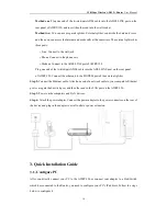
Page 14: ... the ADSL LINE port on the rear panel of AWRT 150 Connect the other end to the MODEM port of the external splitter Step 2 Connect the Ethernet cable Attach one end of a network cable to your computer s Ethernet port or a regular hub switch port and the other end to the LAN port on the AWRT 150 Step 3 Power on the computers and LAN devices Step 4 Attach the power adapter Connect the power adapter t...

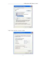
Page 15: ...ser Manual 15 3 1 1 For Windows 2000 or Windows XP as below Step 1 Right Click My Network Places Then select Properties Step 2 Right Click Local Area Connection Then select Properties Step 3 Double click the Internet Protocol TCP IP ...

Page 16: ...150Mbps Wireless ADSL2 Router User Manual 16 Step 4 Configure the IP address After that click OK ...

Page 17: ...P address automatically and Obtain DNS server address automatically in the screen above 3 1 2 For Windows 7 or Windows Vista as below Step 1 Click then select the Open Network and Sharing Center Step 2 Click the Change adapter settings Step 3 Click Local Area Connection with the right button of your mouse Then select Properties ...

Page 18: ...150Mbps Wireless ADSL2 Router User Manual 18 Step 4 Double click the Internet Protocol Version 4 TCP IPv4 Step 5 Select the Obtain an IP address automatically as below Then click OK ...

Page 19: ... below the connection between your PC and the Router has been established If the result displayed is similar to the screen shown below it means that your PC has not connected to the Router You can check it follow the steps below 1 Is the connection between your PC and the Router correct The LEDs of LAN port which you link to the device and the LEDs on your PC s adapter should be lit 2 Is the TCP I...

Page 20: ...llows to use the Web based Utility Start your web browser and type the private IP address of the Router in the URL field 192 168 1 1 After that you will see the screen shown below enter the default User Name admin and the default Password admin And then click OK to access to the Wireless Modem Management Panel screen ...

Page 21: ...150Mbps Wireless ADSL2 Router User Manual 21 ...

Page 22: ...is from 0 to 255 Please input the value provided by your ISP 2 VCI Identifies the virtual channel endpoints in an ATM network The valid range is from 32 to 65535 1 to 31 is reserved for well known protocols Please input the value provided by your ISP 3 NAPT Select this option to Enable Disable the NAPT Network Address Port Translation function for this PVC The NAPT function can be activated or dea...

Page 23: ...means is that RFC 1483 MER allows you to do IP routing with NAT on the LAN side of the CPE router and bridging on the WAN side And when NAT and MER are enabled on the CPE router a customer network of many workstations will appear the same as a single workstation behind a modem If you select this channel mode you will see a screen show in below You can configure IP routing automatically using DHCP ...

Page 24: ... default gateway to internet from this device 5 DHCP Server Setup Here you can select the DHCP Server Status enable or disable and configure IP Address Pool range 6 Wirelss Setup Here you can select Wielress Status enable or disable and configure SSID for your wireless network After configuring all the Settings click Apply to take effect 4 2 Internet Setup Choose Interface Setup you can see the ne...

Page 25: ...default 3 Channel Mode Refer to 4 1 4 Item Status you can configure the item take effect or not 5 802 1q VLAN Virtual LAN VLAN is a group of devices on one or more LANs that are configured so that they can communicate as if they were attached to the same LAN when in fact they are located on a number of different LAN segments Because VLANs are based on logical instead of physical connections it is ...

Page 26: ... Mode a Bridged Ethernet Transparent Bridging Default Bridge Mode b Bridged PPPoE implies Bridged Ethernet In this mode only PPPoE data packets can through the PVC c Disable Bridge After you finish configuration please click Apply to make the settings take effect Then the system will generated a record in the screen below You can also modify or delete the record which you configured 4 2 2 QoS for ...

Page 27: ... VC to take effect For PVCs management you can use ATM QoS to setup each PVC traffic line s priority Click the Modify button to configure VPI VCI Refer to 4 1 QoS Select the Quality of Service types for this Virtual Circuit including CBR Constant Bit Rate UBR Unspecified Bit Rate and VBR Variable Bit Rate These QoS types are all controlled by the parameters specified below including PCR Peak Cell ...

Page 28: ...anual 28 4 2 3 ADSL Setup Choose Interface Setup ADSL Setup menu This feature provides options for user to setup ADSL modulation mode AnnexL option AnnexM option ADSL Capability and ADSL Tone Please configure them according to your needs ...

Page 29: ...o VCs to implement some special network applications such as IPTV The bound port will not be used on other VCs For Example If you want to add a Port Mapping entry binds LAN4 to vc1 please follow these instruction 1 Configure PVC vc1 refer to 4 2 1 2 Select Enable marquee to enable the Port Mapping status click the Save button to make it effective 3 Click one of the Edit button select the LAN WLAN ...

Page 30: ...the Router Internet Info This feature provides running status information of the WAN port The port connect to the Internet and displays the current version of the software LAN Info This item provides information about Modem s LAN port display LAN port s MAC address IP address and current situation of DHCP server AP Info This item provides current running information of Primary AP a Wireless Status...

Page 31: ...wireless communication g SSID Broadcasting You can select enable or disable to enable or disable the broadcast SSID function if the setting of the field is disable wireless client can not obtain this SSID to login in the user have to input the SSID value manually h Security Mode Display whether your security wireless function have been applied System This item provides current running information ...

Page 32: ...tus You can choose enable or disable to enable or disable the Wireless Network Status if you choose Disable the AP function of wireless router will be turned off Radio Band You can select the wireless standards running on your network the default setting is 802 11b g n Mixed Radio Mode You can select radio mode of wireless router the default setting is AP mode SSID SSID Service Set Identifier is y...

Page 33: ...11b g devices Use only when you have a pure router draft 802 11n wireless network Control Sideband It controls your wireless router use the higher or lower channel to tranfer related datas while it working on 40Mhz mode Channel You can set the working channel from 1 to 14 manually to avoid interference 4 5 2 Security Choose Security Setup Access Control you can see the Security screen shown below ...

Page 34: ...ur groups of password you can input all of them or only one of them and the client s password only need to match one group of password Note When WPS function enabled please don t use WEP authentication More details about WPS please refer to 4 5 5 WPA PSK You can select the algorithm you want to use TKIP or AES TKIP means Temporal Key Integrity Protocol which incorporates Message Integrity Code MIC...

Page 35: ...Filter you can see the next screen shown below You can filter wireless users by enabling this function thus unauthorized users can not access the network To disable Wireless Host Filter keep the default setting Disable To enable Wireless Host Filter follow these steps to set Wireless Host Filter Add MAC address you want to control in the MAC address field the format is XX XX XX XX XX XX then click...

Page 36: ...ireless network name SSID and then manually entering a creative yet predictable security key on both the access point and client to prevent unwanted access to their wireless network This whole process requires the users to have the background knowledge of the Wi Fi devices and the ability to make the necessary configuration changes With WPS it will automatically configure a wireless network with a...

Page 37: ...elect Shared Key if you only want to use Shared Key authentication the sender and recipient use a WEP key for authentication Fragmentation Threshold This value specifies the maximum size for a packet before data is fragmented into multiple packets You should leave this value in the 256 to 2346 range In most cases it should remain as its default value of 2346 Setting the Fragmentation Threshold too...

Page 38: ...iability the default setting is Long Preamble 4 6 Security Setup Choose Security Setup Access Control you can see submenus shown below These features make it possible for administrators to control user s access to the Internet protect the networks 4 6 1 MAC Filter You can filter users by enabling this function thus unauthorized users can not access the network Follow these steps below to set MAC f...

Page 39: ...elect the item you want and click Save button 4 6 2 Internet Access Control The rules of Internet Access Control based on source IP port number and protocol Follow these steps to set Internet Access Control Step 1 You can select Default IP Firewall Rule and click Save Settings to enable Internet Access Control function This is only the first step you should continued to create appropriate rules fo...

Page 40: ... in Protocol Template You can select appropriate item and apply it Or you can input protocol type and port number manually click Add button then the item will displayed in the list Step 3 If you want to delete certain item on the list select appropriate item on the list click Del to delete it 4 6 3 DNS Filter DNS filter is able to filter certain domain name such as www sina com Follow these steps ...

Page 41: ... appropriate rules for DNS Filter Step 2 Input description information in the Description field for current access control rule input website name or Domain name in the DNS Key Words field such as www 163 com 4 7 LAN Setup Choose LAN Setup menu and you will see the LAN Setup screen shown below Please configure the parameters for LAN ports according to the descriptions below 4 7 1 LAN IPAddress ...

Page 42: ...Enter the Router s local IP Address then you can access to the Web based Utility via the IP Address the default value is 192 168 1 1 IP Subnet Mask Enter the Router s Subnet Mask the default value is 255 255 255 0 4 7 2 DHCP Server Choose LAN Setup DHCP Server you can see the next screen shown below Select Enabled then the Router will work as a DHCP Server it becomes the default gateway for DHCP c...

Page 43: ...IP Address Pool The DHCP pool is used for allocate IP address by DHCP server the DHCP pool range is also changeable Lease Time Display the rest time that router allows dynamic IP users connect to router DHCP IPAddress Reserving This function is used to allocate reserve IP address to designated MAC address 4 7 3 DHCP Client Info Choose LAN Setup DHCP Server you can see the next screen shown below T...

Page 44: ...rom LAN to WAN FTP Private Port If you need this function please choose Enable Virtual Setting Description Describe current virtual service item Internal Host IPAddress Indicates IP address of the internal host using virtual server Protocol The protocol item supplies several protocols Such as TCP HTTP UDP POP3 etc If you have web server within LAN you can select the HTTP template then the router w...

Page 45: ...ee the next screen shown below DMZ opens all the ports of one computer exposing the computer to the Internet So it should only be used for some special purpose especial for Internet online games Using this function you can select DMZ item and input IP address of DMZ host then click Save For the purpose of security we suggested that using Virtual server instead of DMZ 4 8 3 UPnP Choose Applications...

Page 46: ...ternet games video conferencing Internet calling and so on These applications cannot work with a pure NAT Router Port Triggering is used for some of these applications that can work with an NAT Router Once the Router is configured the operation is as follows 1 A local host makes an outgoing connection using a destination port number defined in the Trigger Port field 2 The Router records this conne...

Page 47: ...0 2038 2050 2051 2085 3010 3030 Forward Protocol The protocol used for Incoming Ports Range either TCP or UDP To add a new rule follow the steps below 1 Select a predefined rule from the Predefined Trigger Rules drop down list then the Trigger Port field and the Forward Ports field will be automatically filled If the Common Applications do not have the application you need enter the Trigger Port a...

Page 48: ... Applications Gateway VPN Pass through you can enable or disable the VPN Pass through function in the screen as shown below VPN is commonly used for encapsulate and encrypt data across the public network For VPN tunnel the router supports IPSEC pass through PPTP pass through and L2TP pass through PPTP Pass through PPTP means the Point to Point Tunneling Protocol select enable to allow PPTP pass th...

Page 49: ...of DynDNS you have to register an account first Other DNS service providers as the same Username Password Type the User Name and Password for your DDNS account Dynamic Domain Name Enter your DDNS server domain name here Status The status of the DDNS service connection is displayed here To set up for DDNS follow these instructions 1 Enable DDNS function by select the Enable marquee 2 Type the User ...

Page 50: ...portion and Host portion The Next hop IP Address This is an IP address of the next hop device and also is the gateway address for local host that allows forwarding data between router and remote network or host Routing Table You can check out all current route items click Del button to delete a route item existed in routing table 4 12 Advanced Setup Choose Advanced Setup menu and you will see the ...

Page 51: ...mote Access and you will see the Remote Access in the next screen show in below This feature allows you to manage your Router from a remote location via the Internet This page is used to enable disable management services for the LAN and WAN Select these services according to actual needs 4 12 3 TR 069 Configuration Choose menu Advanced Setup TR 069 Configuration you can configure the TR 069 funct...

Page 52: ...ction URL Enter the website of ACS which is provided by your ISP User Name Password Enter the User Name and password to login the ACS server Periodic Inform Activate or deactivate the function If Activated the information will be informed to ACS server periodically Periodic Inform Interval Enter the interval time here Path Enter the path that connects to the ACS server Port Enter the port that con...

Page 53: ...ngly recommend you to change the default password Enter a new password and confirm your new password then click Save button to save settings 4 13 2 Upgrade Choose menu System Management Upgrade you can upgrade firmware in the screen Click Browse button and select a File to upgrade After you have selected the appropriate file click Upgrade button to execute upgrade procedure Do not cut off the powe...

Page 54: ...iously 4 13 5 Restore Choose menu System Management Restore and you will see the next screen show in below Click Restore button the Router will erase all of your settings and replace them with the factory defaults make sure you have backup current settings before click this button 4 13 6 WOL Wake up On LAN Choose menu System Management WOL and you will see the next screen show in below Enter host ...

Page 55: ...quirements if your PC s motherboard and NIC do not support sensei function please don t use this function 4 13 7 System Time Choose menu System Management System Time and you will see the next screen show in below The system time is the time used by the device for scheduling services Chose the time zone for you need ...

Page 56: ...able The configuration For Windows 2000 or Windows XP as below Step 1 Click the Wireless Management Enable the wireless network as below Step 2 Click the Security label and select one authentication type in the drop down menu Set the Encryption Type Key Mode Key and Key Renewal as your wish but remember what you stetted Step 3 Click My Network Places with the right button of your mouse Then select...

Page 57: ...ss ADSL2 Router User Manual 57 Step 4 Click Wireless Network Connection with the right button of your mouse Then select View Available Wireless Networks Step 5 Double click the wireless network your AWRT 150 provided ...

Page 58: ...ou stetted before if the wireless network you connecting to requests password The configuration For Windows 7 or Windows Vista as below Step 1 Step 2 refer to the configuration For Windows 2000 or Windows XP Step 3 Click then select the Open Network and Sharing Center ...

Page 59: ... ADSL2 Router User Manual 59 Step 4 Click the SSID of your wireless network and then press the Connect button as below Step 5 Input the key you stetted before if the wireless network you connecting to requests password ...

Page 60: ...ult button with ball point pen or toothpick for 10 seconds the default parameter will be restored after about 3 minutes But the configuration before will be lost So you need to reset it again B Soft Reset Firstly log in the modem configuration interface click the System Management Restore in order then click the Restore as showed below The interface below will appear click OK ...

Page 61: ...odem will enter the configuration interface automatically 5 2 2 How to upgrade the modem Firstly log in the configuration interface then click the System Management Upgrade Browse in order as showed below Select the upgrade firmware in the dialog appeared then click the Open button to use it as showed below ...

Page 62: ...OK in order as showed below Then the modem begin to upgrade as showed below wait for 3 minutes it will enter the management interface automatically 5 2 3 How to connect the modem after setting WLAN password Firstly set password as showed below remember to click Save ...

Page 63: ... ADSL2 Router User Manual 63 Then click the icon on desktop the interface showed below will appear Choose Available Network The interface showed below will appear Then choose the SSID it s Default here as showed below ...

Page 64: ...150Mbps Wireless ADSL2 Router User Manual 64 Double click Default the interface showed below will appear then enter the WLAN password It s 12345678 here as showed below ...

Page 65: ...150Mbps Wireless ADSL2 Router User Manual 65 Click OK and wait for several minutes you will see the interface showed below which means successful connection ...

Page 66: ...150Mbps Wireless ADSL2 Router User Manual 66 Note Similarly when use the computer s client itself to connect just input the password when connecting ...

Page 67: ...ts Four 10 100M Auto Negotiation RJ45 ports Auto MDI MDIX One RJ11 port LEDs Power ADSL Internet WLAN 1 2 3 4 LAN WPS Network Medium 10Base T UTP category 3 4 5 cable 100Base TX UTP category 5 Max line length 6 5Km Data Rates Downstream Up to 24Mbps Upstream Up to 1Mbps System Requirement Internet Explorer 5 0 or later Win 9x ME 2000 XP Vista Windows 7 Physical and Environment Working Temperature ...

Reviews: