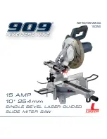
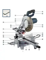
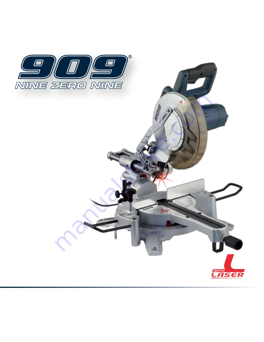
background image

INSTRUCTION MANUAL

10CSMS

15 AMP
10" 254mm

SINGLE BE VEL L ASER GUIDED
SLIDE MItER SAW 
 

Summary of Contents for 10CSMS

Page 1: ...INSTRUCTION MANUAL 10CSMS 15 AMP 10 254mm SINGLE BEVEL LASER GUIDED SLIDE Miter SAW ...

Page 2: ...packaging should be sorted taken to the local recycling centre and disposed of in an environmentally safe way WARNINGS It may be more difficult to see the laser line in conditions of bright sunshine and on certain surfaces Description of symbols 3 Specifications 3 General safety instructions 4 Safety rules for laser lights 5 Additional safety rules for miter saws 6 Accessories 7 Know your product ...

Page 3: ...ction manual Conforms to UL STD 987 Certified to CAN CSA STD No 71 2 08 Specifications Input power 15 Amp No load speed 5500 RPM Voltage 120V 60 Hz Blade size Ø 10 254 mm x Ø 5 8 16 mm bore Number of teeth 40 Miter table angles 0 to 52 left right Bevel cuts 0 to 45 left Straight cut 0 x 0 3 1 4 81 5 mm x 11 5 8 295 mm Miter cut 45 L R x 0 3 1 4 81 5 mm x 8 1 16 205 mm Bevel cut 0 x 45 L 1 5 8 43 m...

Page 4: ... may get caught in moving parts Nonslip footwear is recommended Wear protective hair covering to contain long hair 11 Always use safety glasses Also use face or dust mask if cutting operating is dusty Everyday eyeglasses only have impact resistant lenses they are NOT safety glasses 12 Secure work Use clamps or a vise to hold work when practical It s safer than using your hand and it frees both han...

Page 5: ...ed or deformed saw blades Only use sharp blades When cutting round wood use clamps that prevent the workpiece from turning on both sides of the blade Never use your hands to remove sawdust chips or waste close by the saw blade Use only blades as recommended by the manufacturer Do not use blades manufactured from high speed steel If the table insert is damaged or worn have it replaced by an authori...

Page 6: ...nly for its prescribed purpose Any use other than those mentioned in this Manual will be considered a case of misuse The user and not the manufacturer shall be liable for any damage or injury resulting from such cases of misuse The manufacturer shall not be liable for any changes made to the tool nor for any damage resulting from such changes Even when the tool is used as prescribed it is not poss...

Page 7: ...o rain or use in damp locations Extension cords Replace damaged cords immediately Use of damaged cords can shock burn or electrocute If an extension cord is necessary a cord with adequate size conductors should be used to prevent excessive voltage drop loss of power or overheating The table shows the correct size to use depending on cord length and nameplate amperage rating of tool If in doubt use...

Page 8: ... 12 Guard retraction arm 13 Blade bolt cover 14 Dust bag 15 Bevel lock 16 Bevel scale 18 Fence 19 1 4 6mm Hex key 20 Miter table 21 Miter scale 22 Table insert kerf plate 23 Switch trigger 24 Miter lock 25 Spindle lock 26 Dust extraction port 27 Slide bars 28 Slide lock 29 Trenching depth adjustment screw 30 Trenching stop 31 Trenching depth lock nut 32 45 Bevel adjustment screw 33 0 Bevel adjustm...

Page 9: ...9 1 3 6 10 34 11 12 13 20 21 24 8 9 16 18 22 26 23 27 35 4 7 28 19 36 ...

Page 10: ... locked in the down position the saw is switched off and the plug is removed from the power point Only lift the saw by the carrying handle 7 or outer castings Fig A Do not lift the saw using the guard or operating handle 6 Bench mounting The saw base has holes in each corner to facilitate bench mounting Fig B 1 Mount the saw to a level horizontal bench or work table using bolts not supplied and fi...

Page 11: ...the left and right To adjust the bevel angle loosen the bevel lock and pull out the 0 bevel adjuster 18 Adjust the saw arm to the desired bevel angle WARNING Be sure to tighten the bevel lock before making a cut Failure to do so could result in the saw arm moving during the cut and cause serious personal injury Clamp assembly The clamp assembly 9 can be mounted to the fence either side of the saw ...

Page 12: ...to cut right through a workpiece When the saw arm is lifted the trenching stop can be moved to the left so that the trenching depth adjustment screw 29 contacts the stop as the saw arm is lowered Fig N This restricts the cut to a trench in the workpiece The depth of the trench can be adjusted with the trenching depth adjustment screw 29 Fig O and locked in position with the trenching depth lock nu...

Page 13: ...nd check the blade to table alignment at several points 9 The edge of the set square and the saw blade should be parallel 10 If the saw blade angles away from the set square adjust as follows 11 Use a 13mm wrench or adjustable wrench to loosen the lock nut securing the 0 bevel adjustment screw 33 Fig V Also loosen the bevel lock 15 12 Adjust the 0 bevel adjustment screw 33 with the 6mm hex key to ...

Page 14: ...ER Never try to use a blade larger than the stated capacity of the saw It might come into contact with the blade guards Never use a blade that is too thick to allow the outer blade washer to engage with the flats on the spindle It will prevent the blade screw from properly securing the blade on the spindle Do not use the saw to cut metal or masonry Ensure that any spacers and spindle rings that ma...

Page 15: ... rotation always install the blade with the blade teeth and the arrow printed on the side of the blade pointing down The direction of blade rotation is also stamped with an arrow on the upper blade guard 12 Replace the outer blade washer Fig l 13 Depress the spindle lock button 25 and replace the flat washer and blade bolt 14 Use the 6mm hex key to tighten the blade bolt securely tighten in an ant...

Page 16: ... that is level with the saw table 7 Use the clamp assembly 9 to secure the workpiece wherever possible 8 It is possible to remove the clamp assembly 9 by loosening the clamp assembly lock 10 and moving it to the other side of the table Make sure the clamp assembly lock is tight before using the clamp Fig p 9 Before turning on the saw perform a dry run of the cutting operation to check that there a...

Page 17: ...he clamp assembly lock 10 and moving it to the other side of the table Make sure the clamp assembly lock is tight before using the clamp 10 Before turning on the saw perform a dry run of the cutting operation to check that there are no problems 11 Hold the operating handle 6 firmly and squeeze the switch trigger 23 Allow the blade to reach maximum speed 12 Press the release latch 37 and slowly low...

Page 18: ...e laser light with the on off switch 2 3 Using a Phillips head screwdriver not supplied adjust the position of the laser line by turning the laser pitch control Fig t 4 Adjust until the laser hits the centre of the blade 5 Switch off the laser light Using the laser line generator WARNINGS Do not stare directly at the laser beam Never aim the beam at any person or an object other than the workpiece...

Page 19: ...uthorized repair or mishandling of the tool Power cord maintenance If the supply cord needs replacing the task must be carried out by the manufacturer the manufacturer s agent or an authorised service centre in order to avoid a safety hazard Cleaning 1 Keep the tool s air vents unclogged and clean at all times 2 Remove dust and dirt regularly Cleaning is best done with a soft brush or a rag 3 Re l...

Page 20: ......

Reviews: