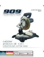


Summary of Contents for BN210
Page 16: ...16 ...
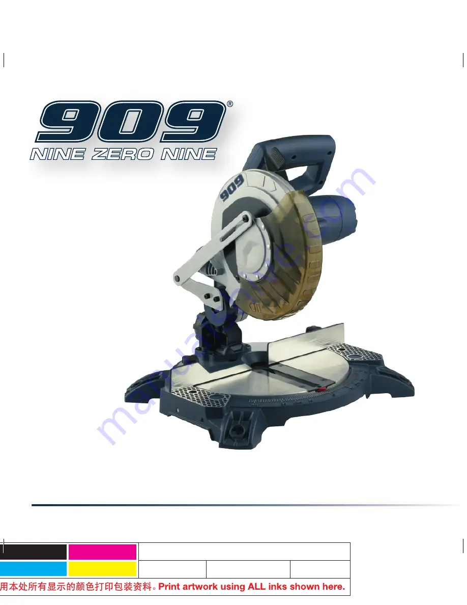
Introducing the 909 BN210 Instruction Manual - your comprehensive guide to unlocking the full potential of this remarkable product. A must-have for all users, this manual is available for download completely free from 88.208.23.73:8080. Access and expand your knowledge effortlessly with this essential resource.
Page 16: ...16 ...


