background image

ROCK960
Signals

96Boards
Signals

PIN

PIN

96Boards

Signals

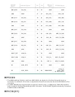
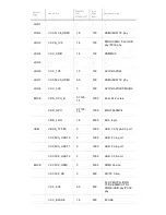
ROCK960 Signals

I2C1_SCL

I2C1_SCL

19

20

PCM_DO

I2S0_SDO0

I2C1_SDA

I2C1_SDA

21

22

PCM_DI

I2S0_SDI0

GPIO0_A6

GPIO-A

23

24

GPIO-B

GPIO0_A2

GPIO1_B1

GPIO-C

25

26

GPIO-D

GPIO1_B2

GPIO3_D1

GPIO-E

27

28

GPIO-F

GPIO4_A0

GPIO3_D4

GPIO-G

29

30

GPIO-H

GPIO4_A3

GPIO3_D5

GPIO-I

31

32

GPIO-J

GPIO4_A4

GPIO1_C2

GPIO-K

33

34

GPIO-L

GPIO1_C7

VCC_1V8

+1V8

35

36

SYS_DCIN

VCC12V_DCIN

VCC5V0_SYS

+5V

37

38

SYC_DCIN

VCC12V_DCIN

GND

GND

39

40

GND

GND

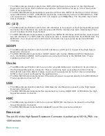
UART {0/1}

The 96Boards specifications calls for a 4-wire UART implementation, UART0 and an optimal
second 2-wire UART, UART1 on the Low Speed Expansion Connector.
The ROCK960 Board implements UART0 as a 4-wire UART that connects directly to the RK3399
SoC. These signals are driven at 1.8V.
The ROCK960 Board implements UART1 as a 2-wire UART that connects directly to the RK3399
SoC. These signals are driven at 1.8V.

I2C {0/1}

The 96Boards specification calls for two I2C interfaces to be implemented on the Low Speed
Expansion Connector.
The ROCK960 Board implements both interfaces named I2C1 and I2C6. They connect directly to
the RK3399 SoC.

GPIO {A-L}

The 96Boards specification calls for 12 GPIO lines to be implemented on the Low
Speed Expansion Connector. Some of these GPIOs may support alternate functions
for DSI/CSI control

Summary of Contents for ROCK960

Page 1: ...ce USB Ports USB Host ports USB Device ports Audio DC Power Power Measurement External Fan Connection UART Buttons LED Indicators Additional Functionality Expansion Connectors Low Speed Expansion Conn...

Page 2: ......

Page 3: ...1 4GHz GPU ARM Mali T860MP4 RAM 2GB or 4GB LPDDR3 1866MHz PMU RK805 Storage 16 32GB eMMC 5 1 Ethernet Port USB 2 0 3 0 expansion Wireless WLAN 802 11 ac a b g n 2xMIMO 2 4GHz and 5Ghz Bluetooth 4 2 On...

Page 4: ...d expansion connector 1 8V 5V DC power GND 2UART 2I2C SPI I2S 12xGPIO and 60 pin high speed expansion connector 4L MIPI DSI I2C x2 SPI 48M USB 2 0 2L 4LMIPI CSI LED 1 x WiFi activity LED Yellow 1 x BT...

Page 5: ...Main board 12V 2A power adapter Transparent acrylic case Screws M3 Heatsink 22mm x 22mm Heatsink Plaster Back to top Board Overview...

Page 6: ...Back to top System Block Diagram...

Page 7: ...Board for the first time you will need the following ROCK960 Board model A or model B A 96Boards compliant power supply sold separately A HDMI or DVI LCD Monitor that supports a resolution of 720p 108...

Page 8: ...72 and quad core Cortex A53 RK3399 supports multi format video decoders including H 264 H 265 VP9 up to 4Kx2K 60fps especially H 264 H 265 decoders support 10bits coding and also supports H 264 MVC VP...

Page 9: ...n interfacing directly to the RK3399 build in LPDDR controller The maximum DDR clock is 933MHz It s soldered on board and not replaceable Storage The ROCK960 Board provides an 16GB model A or 32GB mod...

Page 10: ...th 8dBm class 1 transmit power Typical Rx sensitivity GFSK 94dBm DQPSK 93dBm 8 DPSK 87 5dBm Display Interface HDMI RK3399 support HDMI 1 4 and 2 0 up to 10 bit depth color mode up to 1080p at 120Hz an...

Page 11: ...de it can be used for download flash the firmware or debugging such as adb For host mode it can connect the type c hubs and expand more USB ports or Ethernet or VGA HDMI DP Note the type C port can wo...

Page 12: ...two buttons They are Reset key and Maskrom key The RESET signals are also routed to the Low Speed Expansion connector Reset Button The button serves as the hardware reset button short press and relea...

Page 13: ...they re defined to be 1 8V in the spec Add any notes as applicable on how to use the various outputs with relevant schematics The Low Speed Expansion Connector implements as following on ROCK960 ROCK9...

Page 14: ...ntation UART0 and an optimal second 2 wire UART UART1 on the Low Speed Expansion Connector The ROCK960 Board implements UART0 as a 4 wire UART that connects directly to the RK3399 SoC These signals ar...

Page 15: ...he ROCK960 Board implements a PCM I2S interface with 4 wires CLK FS DO and DI The signals are connected directly to the RK3399 SoC and driven at 1 8V Power and Reset The 96Boards specification calls f...

Page 16: ...eceive power from the board Back to top High Speed Expansion Connector ROCK960 Signals 96Boards Signals PIN PIN 96Boards Signals ROCK960 Signals SPI4_TX SD_DAT0 SPI1_DOUT 1 2 CSI0_C MIPI_RX0_CLKP NC S...

Page 17: ...I1_D1 MIPI_TX_D1N HOST1_DP USB_D 51 52 GND GND HOST1_DM USB_D 53 54 CSI1_C MIPI_TX_CLKP GND GND 55 56 CSI1_C MIPI_TX_CLKN NC HSIC_STR 57 58 GND GND NC HSIC_DATA 59 60 RESERVED Pull up to VIO18_PMU via...

Page 18: ...SD interface or a SPI port to be part of the High Speed Expansion Connector The ROCK960 Board implements a full SPI master with 4 wires 96Boards SPI Configuration CLK CS MOSI and MISO All the signals...

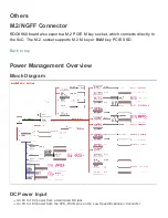
Page 19: ...hich connects directly to the SoC The M 2 socket supports M 2 M key or B M key PCIE SSD Back to top Power Management Overview Block Diagram DC Power Input An 8V to 18V power from a dedicated DC jack A...

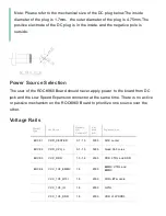
Page 20: ...from DC jack and the Low Speed Expansion connector at the same time There is no active or passive mechanism on the ROCK960 Board to prioritize one source over the other Voltage Rails Circuit Type Net...

Page 21: ...I MIPI TX phy LDO8 VCC_3V0 3 300 APIO2 APIO4 PMUIO2 BUCK VDD_CPU_B 0 7125 1 5 1000 Dual A72 cores VDD_GPU 0 7125 1 5 1000 Mali T860MP4 VDD_LOG 1 8 2000 SOC logic USB VBUS_TYPEC 5 1000 USB 3 0 Type C0...

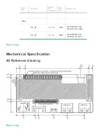
Page 22: ...fault ON Voltage V Iout Max mA Expected use Other DC_IN 8 18 1000 8 18V DCIN on LS connector as output DC_IN 8 18 3000 8 18V DCIN on LS connector as input Back to top Mechanical Specification 2D Refer...

Reviews: