


Technical Bulletin
1370
23023
code
a.b.s.
S.r.l. (Milan) Italy
Lombardia street 310, 20861 Brugherio
Tel. +39 039 839631 - Fax. +39 039 8396349
e-mail:info@absfire.it - www.absfire.it - Capital 2.000.000
Technical data are subject to modification
for improvements without prior notice
Data Sheet
Code
Date
Check
Rev
Pag.
Marine Con.Box
23023
25/05/15
benz
3/
benz
3/5
Technical specification operating Control Box.
Use instruction.
Control Box consist of two units, a central unit CPU with LCD large backlit display
designed to be installed in engine compartments and remote unit to activate and
control the system from the dash board.
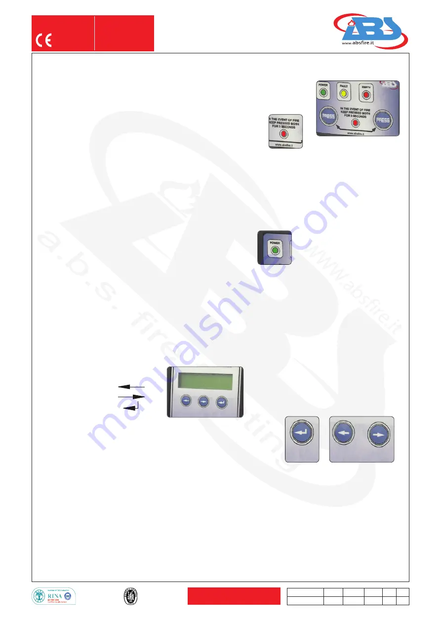
The central unit receives activation signal from the remote unit pushing
down simultaneously both buttons for 3 sec (
pict. 1
).
The central
red
LED flashes, until the system operated after it stop to flash.
During the discharge, the pressure switch connected to the system will change its condition (it close the contact) and turn on
the red led “EMPTY” permanently, until the system will be reset.
The red led “
EMPTY
” is switched on even if there are leaks from the cylinder. In this case, call an authorised service
company of ABS.
The yellow led “
FAULT
” shows an anomaly from the
IN1 - IN2 - IN3 - IN4 - IN5
, and according to the set delays on the
outputs, it will generate the activation of the
OUTPUT OUT1 - OUT2 - OUT3 - OUT4 - OUT5.
After activation of the outputs,
the yellow led “
FAULT
” will switch off, and the red led “
EMPTY
”, will be switched on.
The green led “
POWER
” indicates that the system is correctly operating
and it will be switched off in case of malfunction or discharge.
- Signal input:
IN1
Pressure switch (
N.C.
)
IN2
Temperature detector
IN3
Thermosensittive cable
IN4
Remote activation (Button underglass)
IN5
Further alarm remote available
- Output control relay:
OUT1
Electric actuator
OUT2
Solenoid fuel electro valve solenoid fuel tank
OUT3
Closed shutters ventilation of the engine compartment
OUT4
Solenoid gas kitchen system (
N.O.
)
OUT5
Acoustic indicator
Program CPU
LX
Decreases
RX
Increases
Send Change screen
Program level 1
Push the button
SEND
(
pict. 2
) for 10 sec. until entry in the function level 1.
Select the language with button
RX
or
LX
(
pict. 3
).
Push “
SEND
” to change the screen.
Push the button
RX
or
LX
to enable or disable the system.
Program level 2
At the finish of the program level 1 “end input” push the button
RX
and
LX
together
(
pict. 3
) for 10 sec. until entry in the function level 2.
With button
RX
or
LX
can enable or disable the function of level 2.
(
pict. 1
)
(
pict. 2
)
(
pict. 3
)
LX
SEND
RX


