


Technical Bulletin
1370
23023
code
a.b.s.
S.r.l. (Milan) Italy
Lombardia street 310, 20861 Brugherio
Tel. +39 039 839631 - Fax. +39 039 8396349
e-mail:info@absfire.it - www.absfire.it - Capital 2.000.000
Technical data are subject to modification
for improvements without prior notice
Data Sheet
Code
Date
Check
Rev
Pag.
Marine Con.Box
23023
25/05/15
benz
3/
benz
4/5
FUNCTION LEVEL 2
FUNCTION INPUT 1
: RX Enable
-
LX Disable
FUNCTION INPUT 2
: RX Enable
-
LX Disable
FUNCTION INPUT 3
: RX Enable
-
LX Disable
FUNCTION INPUT 4
: RX Enable
-
LX Disable
FUNCTION INPUT 5
: RX Enable
-
LX Disable
FUNCTION OUTPUT 1
: RX Enable
-
LX Disable
FUNCTION OUTPUT 2
: RX Enable
-
LX Disable
FUNCTION OUTPUT 3
: RX Enable
-
LX Disable
FUNCTION OUTPUT 4
: RX Enable
-
LX Disable
FUNCTION OUTPUT 5
: RX Enable
-
LX Disable
DELAY OUTPUT 1
: RX Increase from 0 >99
-
LX Decrease from 0 <99
DELAY OUTPUT 2
: RX Increase from 0 >99
-
LX Decrease from 0 <99
DELAY OUTPUT 3
: RX Increase from 0 >99
-
LX Decrease from 0 <99
DELAY OUTPUT 4
: RX Increase from 0 >99
-
LX Decrease from 0 <99
DELAY OUTPUT 5
: RX Increase from 0 >99
-
LX Decrease from 0 <99
Descriptions that appear on the display
www.absfire.it (immediately after power-up)
OPERATING SYSTEM
SYSTEM DISCHARGE
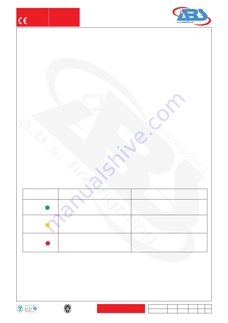
COLOR
SYSTEM STATUS
PERFORM
LED
DESCRIPTION
OPERATION
Dash board led
Status System OK.
Devices are properly
installed and fully functional.
Green
Led
POWER
NOTHING
The system has been activated, the switch
has been activated (and not yet released)
or thermocables are in short circuit.
Yellow
Led
FAULT
Pressurizzed the fire extinguisher
Be sure that there are no leaks or replace
and reinstall the electric actuator.
Red
Led
EMPTY
WARNING
SYSTEM FAULT
Low-pressure on the fire extinguisher
or electric actuator damaged
or wires are not connected properly.
Low-pressure on the fire extinguisher or verify the
functionality of the pressure switch with a tester or
electric actuator damaged to be replaced or wires are
not connected properly to be reconnected.


