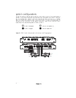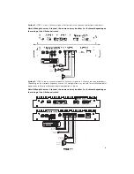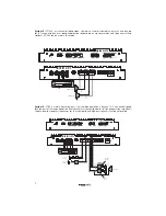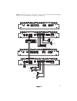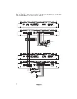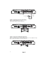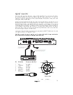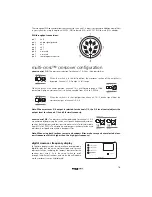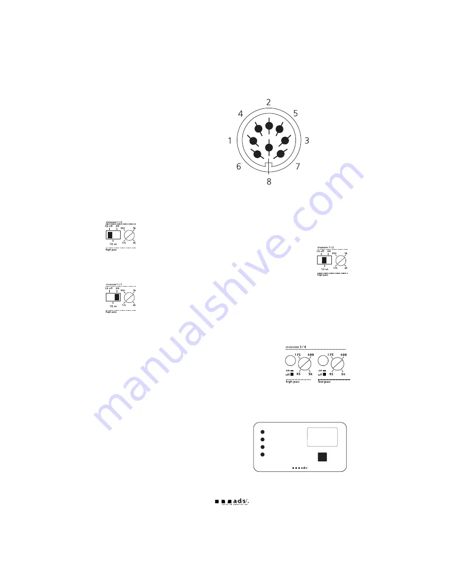
The throughput DIN connector allows easy access to Channels 1-4 inputs for routing to additional amplifiers
in your system by using the optional AC202 (DIN to female RCA) or AC207 (DIN to male RCA) adapter.
DIN throughput connections:
pin 1
ch 4
pin 2
audio signal ground
pin 3
ch 2
pin 4
ch 3
pin 5
ch 1
pin 6
not used
pin 7
not used
pin 8
remote power control
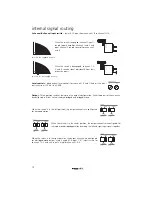
multi-cross™ crossover configuration
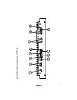
xover control 1/2-
The crossover selection for channels 1 & 2 has three possibilities:
When the switch is in the left position, the crossover section of the amplifier is
bypassed. Channels 1 & 2 output is full range.
When the switch is the center position, channels 1 & 2 are filtered through a 12dB
per octave high-pass crossover that is infinitely variable from 45Hz to 5,000Hz.
When the switch is in the right position, channels 1 & 2 receive signal from the
crossover output of channels 3 & 4.
Note: When crossover 3/4 output is selected for channels 1/2, the 3/4 level control adjusts the
output level for channels 1/2 and 3/4 simultaneously.
xover control 3/4-
The crossover sections dedicated for channels 3 & 4
are activated by depressing the switch next to each frequency adjustment
control. Both high-pass and low-pass crossovers are infinitely adjustable
from 45Hz to 5,000Hz. The high-pass and low-pass sections may be used
individually or together to create a bandpass filter.
Note: When using both sections to create a bandpass filter, make sure you have selected a low-
pass frequency which is higher than the high-pass frequency!
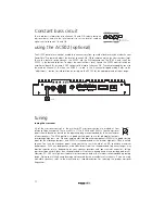
digital crossover frequency display
To facilitate quicker system tuning, we have incorporated a
digital display that shows the crossover frequency for each
crossover section, including the lowpass crossover for the
constant bass circuit. Push the select switch to scroll
through the different sections, and a blue led will indicate
which crossover is currently displayed.
16
ch 1/2 high pass
ch 3/4 high pass
ch 3/4 low pass
select
constant bass
constant bass

