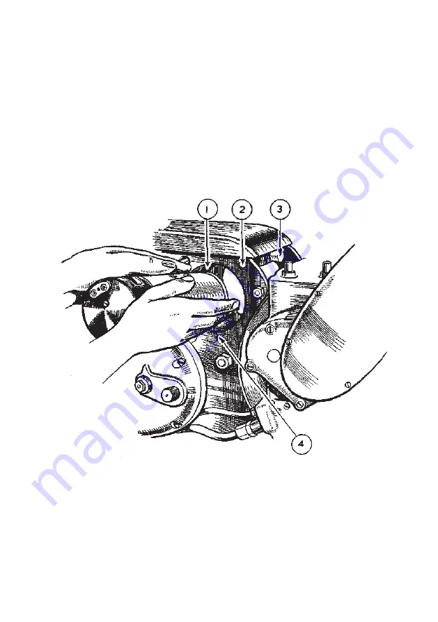
TO REMOVE THE DYNAMO
Remove the left side foot rest arm.
Place a tray under primary chaincase to catch the oil.
Remove chaincase band binding screw and remove metal band and also endless rubber
band.
Remove nut and washer in centre of chaincase when outer half can be taken away.
Remove spring circlip, locking plate and nut securing dynamo sprocket and withdraw
sprocket with a suitable tool. (Use spanner 017254 to hold sprocket while nut is being
slackened, this relieves the dynamo shaft of all bending strain).
Detach dynamo cables and loosen dynamo clamping bolt to fullest extent.
Twist dynamo by hand until the locating strip on its body is in line with the keyway
cutaway in the rear engine plate housing the dynamo, in which position same can be
withdrawn tilting upwards to clear gear box while doing so (see illustration 31.)
To re-fit the dynamo, reverse the foregoing taking care to accurately locate the dynamo
sprocket key when applying the sprocket. See separate instructions for correct dynamo
chain adjustment and re-fitting outer half of chaincase. Ensure that dynamo sprocket
securing nut is well tightened before refitting locking plate and retaining circlip.
1.
2.
STRAP (metal) CLAMPING DYNAMO IN
POSITION.
SQUARE CROSSBAR, TO ACCOMMODATE
THE BOLT WHICH TIGHTENS DYNAMO
CLAMPING STRAP.
3.
4.
BOLT, FOR TIGHTENING DYNAMO
CLAMPING STRAP.
HINGE PIN FOR ANCHORING LOWER
END OF DYNAMO CLAMPING STRAP
Illustration 31
A . V . C . U N I T
Although the voltage regulator and the cut-out are combined structurally, they are
electrically separate.
The regulator is set to maintain a pre-determined generator voltage at all speeds and
regulates the output of the dynamo to the battery according to the state of charge of the
battery. The charge rate is at its maximum when the battery is discharged, automatically
tapering off to a minimum as the battery becomes charged and its voltage rises.
72
www.ajs-matchless.info
Summary of Contents for 16MS
Page 2: ...w w w a j s m a t c h l e s s i n f o...
Page 39: ...Illustration 13 Carburetter details in assembly order 37 w w w a j s m a t c h l e s s i n f o...
Page 54: ...Illustration 18 Exploded view of Teledraulic Forks 52 w w w a j s m a t c h l e s s i n f o...
Page 58: ...Illustration 20 Ghost view of TELEDRAULIC leg 56 w w w a j s m a t c h l e s s i n f o...
Page 79: ...Illustration 35 Wiring diagram 77 w w w a j s m a t c h l e s s i n f o...
Page 89: ...TOOL KIT Illustration 37 87 w w w a j s m a t c h l e s s i n f o...


