Furnace Installation and Owners Manual
24
LDJ620_E01_R03_2006.03
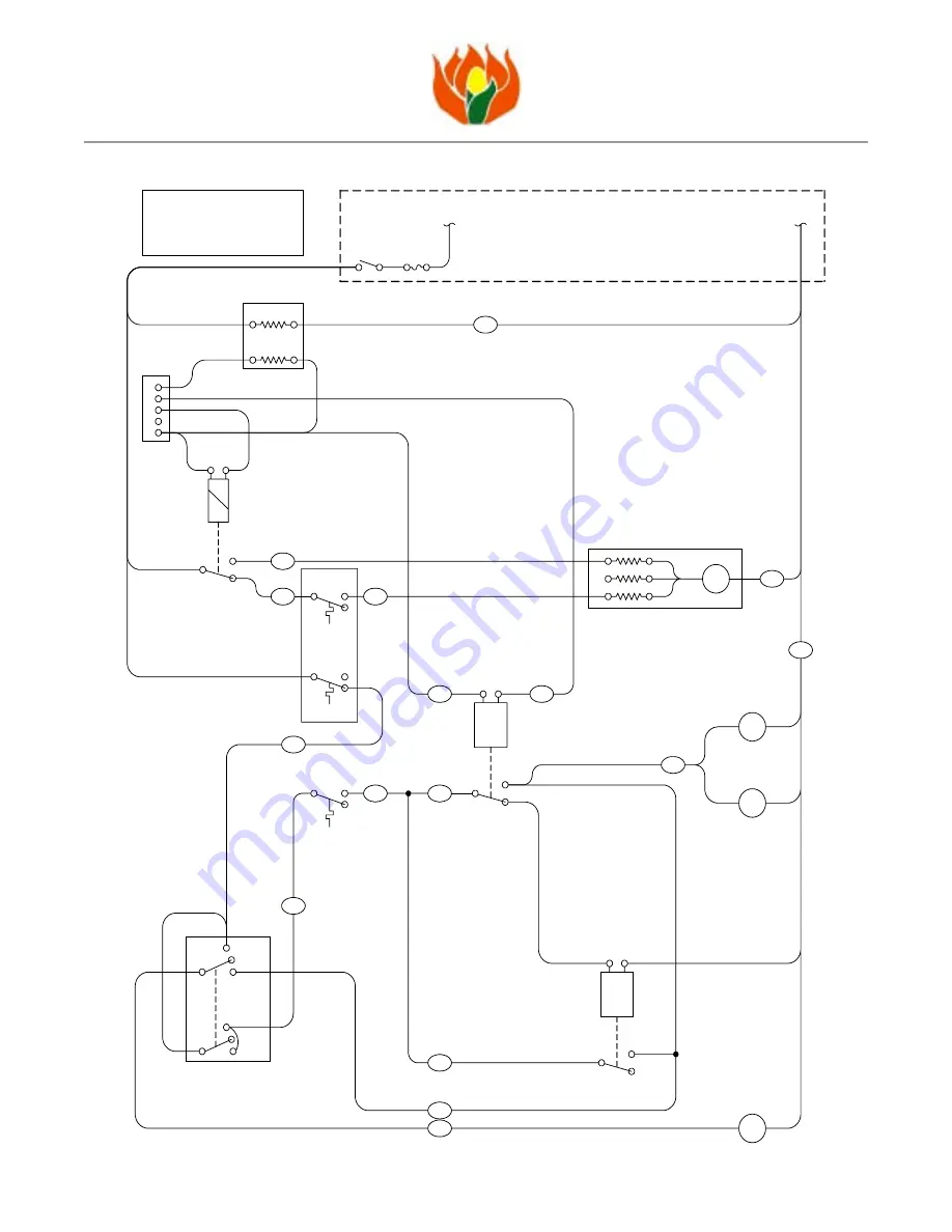
Models LDJ620-9 and LDJ620-10
W
I R I N G
D
I A G R A M
: L D J 6 2 0 - 9 1 0 0 , 0 0 0 B T U F
U R N A C E
BLUE
BLUE
BK
Heat Relay (HR)
NC
NO
Relay
7
2
BK
RD
YL
H-BK
BK
WH
RD
BR
BR
Fan Control
Switch
Low Limit
Switch
Closes on
temp. rise
210°F
155°F
High Limit
Switch
120V
24V
Transformer
G
W
C
Y
R
Fan
Relay
87A
87
30
Thermostat
connections
Low Fire
Timer/Relay (LF)
7
2
timer
M
Combustion
Blower Motor
3-Speed Fan Motor
M
BLK
RED
BLU
High
Low
Med
PUR
120V
NEUTRAL
85
86
R: 24V power supply to thermostat
W: Heat signal from thermostat
Y: A/C signal from thermostat
G: Fan full time signal from thermostat
C: 24V Common
120V
HOT
Fuse
10A
Disconnect
1,8
3,6
4
NC
NO
1,8
3,6
OR
M
Furnace Auger
Motor
M
Bin Auger
Motor
(Installed By Others)
WH
H-BK
Heat Control Switch
START
OFF
RUN
START
OFF
RUN
BLU
or WH


