6
FRONT PANEL
RECEIVER
Front Panel
q
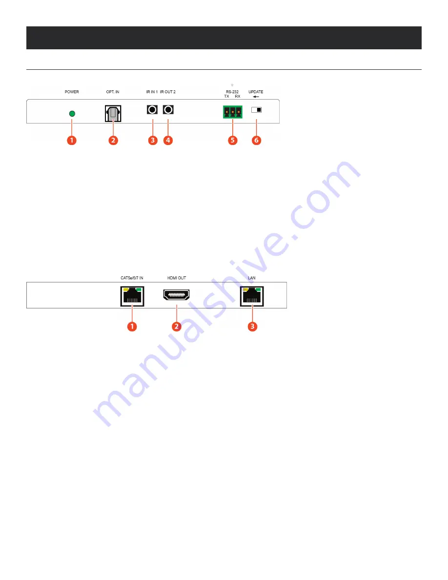
POWER LED:
This power LED will illuminate when receiving power from the transmitter.
w
OPTICAL IN:
Connects with an optical audio source as an optical audio return which sends audio to the Transmitter.
e
IR IN 1:
IR IN 1 is considered an IR receiver which connects to the supplied IR Receiver cables for IR signal reception. Ensure that
remote being used is within the direct line-of-sight of the IR Extender.
r
IR OUT 2:
IR Out 2 is considered an IR BLASTER which connects to the supplied IR Blaster cable for IR signal transmission. Place
the IR Blaster in direct line-of-sight of the equipment to be controlled.
t
RS-232:
Connects to the device that is to be controlled (via RS-232 terminal connected with a D-Sub 9-pin cable) by ASCII commands.
y
UPDATE:
When updating the firmware, the switch should be moved to the left side. As indicated by the arrows on the case.
BACK Panel
q
CAT5E/6/7 IN:
Connects to the transmitter unit with a single CAT5e/6/7 cable for transmission of all data signals and power.
w
HDMI OUT:
Connects to the HDMI sink equipment such as a display.
e
LAN:
Connects to your local LAN or device.
A
NEU
VIDEO
Summary of Contents for ANI-1082UHD-KIT
Page 33: ...CONNECTION DIAGRAM CONNECTION DIAGRAM MAIN UNIT A NEUVIDEO 31 ...
Page 34: ...32 CONNECTION AND INSTALLATION CONNECTION AND INSTALLATION RECEIVER A NEUVIDEO ...
Page 35: ...IR CABLE PIN ASSIGNMENT IR Cable Pin Assignment A NEUVIDEO 33 ...


