TABLE OF CONTENTS
A
NEU
VIDEO
1
CONTENTS
INTRODUCTION & PACKAGE CONTENTS .................................1
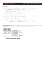
FEATURES & CABLE TERMINATION ......................................... 2
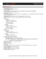
SPECIFICATIONS ........................................................................ 3
OPERATION CONTROLS & FUNCTIONS ................................... 4
DESCRIPTIONS ........................................................................... 6
CONNECTION DIAGRAM ........................................................... 7
WIDEBAND IR .............................................................................. 8
INTRODUCTION
The ANI-HDR-70 18Gbps HDMI HDBaseT
™
Extender Transmitter/
Receiver kit is a tool which can extend your HDMI signal over
230ft (70M) to a compatible display for high dynamic range
(HDR) formats. It is designed to convert HDMI signal to standard
HDBaseT
™
signal which can be transmitted by LAN cable and is
HDCP 2.2 compliant and supports 4K/UHD video @60Hz with
4:4:4 chroma sampling, as well as HDMI data rates up to 18Gbps.
The ANI-HDR-70 provides HDMI transmission up to 230 ft (70M)
for 1080p video and up to 130ft (40M) for 4K HDR over CAT6a/7
cable. It also supports Transfer Bidirectional Infrared control signal
together with the HDMI signal so you can control the Source in
the Sink side which is 230ft outside, also you can control the
Sink in the Source side which is 230ft outside by using the HDMI
Extender. These units feature visually lossless compression with
no latency to enable HDR and 4K/60 4:4:4 video signal extension
over HDBaseT
™
. This product come with a 3 year warranty.
PACKAGE CONTENTS
Before attempting to use this unit, please check the packaging and
make sure the following items are contained in the shipping carton:
• ANI-HDR-70 HDMI 18Gbps Transmitter
• ANI-HDR-70 HDMI 18Gbps Receiver
• (2) Wideband IR Tx
• (2) Wideband IR Rx
• 24V/1A Power Adaptor
• Users Guide
Surge protection device recommended
This product contains sensitive electrical components that
may be damaged by electrical spikes, surges, electric shock,
lightning strikes, etc. Use of a surge protection systems is highly
recommended in order to protect and extend the life of your
equipment.
SAFETY PRECAUTIONS
Please read all instructions before attempting to unpack, install or
operate this equipment and before connecting the power supply.
Please keep the following in mind as you unpack and install this
equipment:
• Always follow basic safety precautions to reduce the risk of fire,
electrical shock and injury to persons.
• To prevent fire or shock hazard, do not expose the unit to rain,
moisture or install this product near water.
• Never spill liquid of any kind on or into this product.
• Never push an object of any kind into this product through any
openings or empty slots in the unit, as you may damage parts
inside the unit.
• Do not attach the power supply cabling to building surfaces.
• Use only the supplied power supply unit (PSU). Do not use the
PSU if it is damaged.
• Do not allow anything to rest on the power cabling or allow any
weight to be placed upon it or any person walk on it.
• To protect the unit from overheating, do not block any vents or
openings in the unit housing that provide ventilation and allow for
sufficient space for air to circulate around the unit.
DISCLAIMERS
The information in this manual has been carefully checked and
is believed to be accurate. We assume no responsibility for any
infringements of patents or other rights of third parties which may
result from its use.
We assume no responsibility for any inaccuracies that may be
contained in this document. We make no commitment to update or
to keep current the information contained in this document.
We reserve the right to make improvements to this document and/
or product at any time and without notice.
COPYRIGHT NOTICE
No part of this document may be reproduced, transmitted,
transcribed, stored in a retrieval system, or any of its part translated
into any language or computer file, in any form or by any means
— electronic, mechanical, magnetic, optical, chemical, manual, or
otherwise — without the express written permission and consent.
© Copyright 2018. All Rights Reserved.
Version 1.4 JAN 2018
TRADEMARK ACKNOWLEDGMENTS
All products or service names mentioned in this document may be
trademarks of the companies with which they are associated.


