510
Indoor / 510 Outdoor Service Manual
Ver. 1.00
40
CONFIDENTIAL
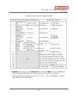
Error Code
Diagnosis
Checkpoint
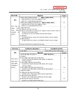
111
Error code is
shown after
three
failed
attempts
at
ignition
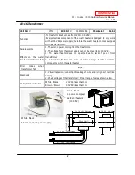
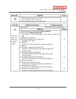
5 Disconnected/damaged O.H.C.F.
(Refer to section 10-13)
Visual inspection: connection/breakage of wires.
Normal: 1
Ω
or less between blue & blue
C2
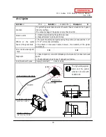
6 Disconnected/damaged hi-limit switch. (Refer to section 10-12)
Visual inspection: connection/breakage of wires.
Normal: 1
Ω
or less between blue & blue
C1
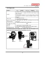
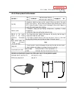
7 Inspect flame rod
[1] Check for any soot on the rod.
[2] Check the connection of ground wire; make sure there is firm contact to
the ground of the water heater.
(in this case, the wire is contacted to the manifold surface.)
[3] PCB fault
During operation: more than 1
μ
A through the flame rod wire (orange)
[4] Flame rod fault
During operation: more than 1
μ
A through the flame rod wire (orange)
I
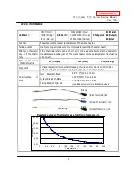
8 Check if hi-limit switch is properly functioning.
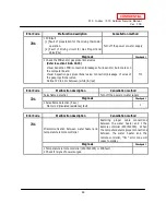
Error Code
Malfunction description
Cancellation method
121
Error code is
shown after
three failed
attempts at
ignition
Loss of flame
Turn off the power or water supply
Diagnosis
Checkpoint
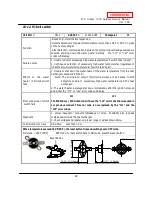
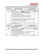
1 Check gas supply and pressure (Refer to section 1)
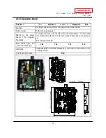
2 PCB fault
[1] No voltage to gas main solenoid valve (MV)
Normal: 78 to 100 VDC between COM (blue) & #3 (light blue)
(during operation)
[2] No voltage to gas solenoid valve (SV
2
)
Normal: 78 to 100 VDC between COM (blue) & #53 (orange)
(during operation)
[3] No voltage to gas proportional valve (VG
0
)
Normal: 1 to 15 VDC between white & red (during operation)
C
H1
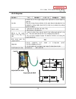
3 Gas solenoid fault
[1] Main gas solenoid valve (MV) fault
Normal: 0.9 to 1.3 k
Ω
between COM (blue) & #3 (light blue)
[2] Gas solenoid valve (SV
2
) fault
Normal: 1.3 to 1.9 k
Ω
between COM (blue) & #53 (orange)
[3] Gas proportional valve (VG
0
) fault
Normal: 1 to 15 VDC between white & red
C
H1

