510 Indoor / 510 Outdoor Service Manual
Ver. 1.00
8
CONFIDENTIAL
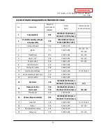
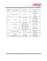
4. List of main components in the interior view
No.
Description
Items# in
components
diagram
AOS
Part #
Common parts
for other models
1
Case assembly
001
319143-151 (510 Indoor)
319143-211 (510 Outdoor)
2
Manifold assembly with gas
valve assembly
102
319143-046 (LP model)
319143-368 (NA model)
3
Computer board
701
319143-179
4
Igniter
711
319143-052
110, 310, 710,
910, 520
5
Transformer
702
319143-182
110, 310
6
Water inlet
404
319143-193
110, 310
7
Water outlet
409
319143-194
110, 310
8
Inlet thermistor
407
319143-085
9
Mixing thermistor
408
319143-190
10
Overheat cut-off fuse
413
319143-149
110, 310, 910
11
Burner assembly (Burners)
101
319143-030
12
Hi-limit switch
412
319143-095
13
Fan motor
103
319143-043 (510 Indoor)
319143-217 (510 Outdoor)
310
14
Freeze protection
thermostat
713
319143-185 (510 Indoor)
710
319143-210 (510 Outdoor)
110, 310
15
Flow sensor
402
319143-178
16
Heat exchanger assembly
401
319143-369 (510 Indoor)
319143-177 (510 Outdoor)
17
Gas inlet
118
319143-050
110, 310, 520
18
Heater
414
319143-200
110, 310
19
Flow adjustment valve
402
319143-178
20
Surge box
703
319143-168
110, 310


