background image

2

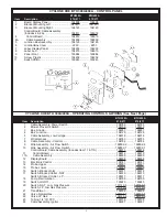
BTH 300A

BTH 400A

Item Description

970/971

970/971

1

Cleanout Gasket .............. 99038 ............ 99038

2

Cover, Cleanout ............... 99037 ............ 99037

3

Cover, Left ...................... 194748 .......... 194748

4

Cover, Right .................... 194749 .......... 194749

5

Drain Valve ..................... 26273-4 ........ 26273-4

7

Labels:
800 Help Line ................. 190600 .......... 190600
C.E.C. ............................. 42985 ............ 42985
Cleanout .......................... 78754 ............ 78754
ECO .............................. 192282-1 ...... 192282-1
Electronic Ignition ............ 77860 ............ 77860
Flammable Vapors ......... 193302 .......... 193302
Lighting & Operating ....... 194548 .......... 194548
Relief Valve ..................... 191068 .......... 191068
UL................................... 192870 .......... 192870
Ultra Coat ....................... 193860 .......... 193860
Warning .......................... 193912 .......... 193912
Water Inlet ....................... 94519 ............ 94519
Water Outlet .................... 94518 ............ 94518
Wiring Diagram ............... 194772 .......... 194772

8

Panel, Back .................... 194750 .......... 194750

9

Temperature and
Pressure Relief Valve ...... 99383-3 ........ 99383-3

CYCLONE XHE BTH 300A/400A - PARTS LIST

NOTE:  

Underlined parts are recommended

stock items for emergency replacement.
Consider gas used in your area only.

 *Not illustrated.

Standard hardware items may be
purchased locally.

Summary of Contents for 970 Series

Page 1: ...0 PRINTED IN U S A 0604 195788 001 BLOWER BURNERASSEMBLY See Page 7 GAS VALVE See Page 5 RECIRCULATINGSYSTEM See Page 5 OPERATINGCONTROLWIRING See Page 4 CONTROLPANEL See Page 3 POWEREDANODEASSEMBLY S...

Page 2: ...FlammableVapors 193302 193302 Lighting Operating 194548 194548 ReliefValve 191068 191068 UL 192870 192870 Ultra Coat 193860 193860 Warning 193912 193912 Water Inlet 94519 94519 Water Outlet 94518 9451...

Page 3: ...AT 194910 194910 Switch Blocked Outlet LP 195017 195017 18 Pump Recirculation 194799 194799 19 Switch On Off 193243 193243 20 Switch NAT Low Gas Pressure 191149 6 191149 6 Switch LP Low Gas Pressure 1...

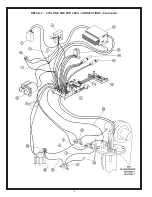
Page 4: ...4 DETAIL 2 CYCLONE XHE BTH 300A CONNECTIONS Continued...

Page 5: ...194924 194924 10 Tube Inlet 194820 194820 11 Vent Automatic Air 194830 194830 Standard hardware items may be purchased locally RECIRCULATING SYSTEM BTH 300A BTH 400A Item Description 970 971 970 971...

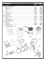
Page 6: ...2696 192696 9 Hose Clamp 4 5 192697 192697 VENT KIT PARTS 10 Elboww Screen 192815 195009 11 Elbow 45 x 3 5 dia 181901 181901 12 Screen 181662 195008 13 IntakeTerminal 182167 182167 14 Wall Plates 2 Re...

Page 7: ...194817 5 Gasket Burner 194777 195016 6 Gasket Viewport 194827 194827 7 Ignitor 192334 192334 8 Screw 8 18 x 1 2 192698 192698 9 Screw Socket Head Cap 192515 192515 10 Screw Truss Hd Mach 1 4 20 x 2 00...

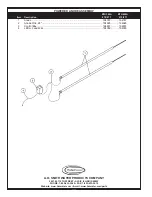
Page 8: ...ONE 1 800 433 2545 FAX 1 800 433 2515 Website www hotwater com E mail www hotwater com parts BTH 300A BTH 400A Item Description 970 971 970 971 1 Anode 194787 194787 2 Anode Wire 28 194925 194925 3 Co...

Reviews: