16
WATER CONNECTIONS
Water piping must be installed in accordance with the instructions
in this manual and all local plumbing codes having jurisdiction.
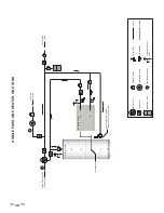
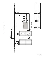
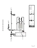
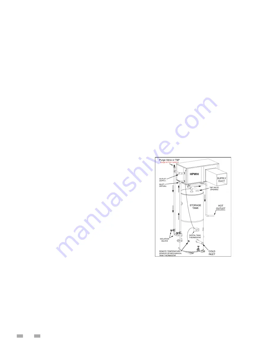
See Figure 7 and Figure 8 and the Piping Diagrams on page 28 as
a reference for these instructions.
INSTALLATION INSTRUCTIONS
1.
This HPWH unit is not designed to supply hot water directly
to hot water fi xtures. The HPWH unit must be installed with a
separate storage tank as shown in the water piping diagrams
in this instruction manual.
2. Water lines installed between the storage tank and the
HPWH unit MUST NOT be less than the water pipe
connection sizes on the unit. See Table 4 on page 12.
3. The HPWH should be plumbed directly to the storage
tank.
4. The cold water supply must be connected directly to the
storage tank at a low connection port on the storage tank
on single tank and two tank preheat piping confi gurations
for optimal effi
ciency. See Figure 7 and Figure 8..
5. The cold water supply MUST NOT be connected the inlet
(entering/return) water line to the HPWH unit.
6. The outlet (supply) water from the HPWH unit should
connect to a middle or lower port on the storage tank.
7.
The inlet (return) water from the HPWH unit should connect
to a port on the storage tank lower than the outlet.
8. A heat trap should be installed between the storage tank
and the backup water heater on two tank preheat systems.
See Piping Diagram on page 28.
9. A T&P valve must be installed in the designated opening
on the storage tank per the tank manufacturer’s requirements.
See Temperature - Pressure Relief Valve on page 13.
10. For optimal performance minimize the equivalent length
of water piping between the HPWH and storage tank.
11. Building hot water recirculation loop should be
connected to the inlet of the backup water heater on
two tank preheat confi gurations or to the storage tank on
single tank confi gurations. The recirculating pump MUST
BE controlled by a fi eld supplied thermostat installed in
the building recirculation return line near the storage
tank or back up heater. The thermostat should stop pump
operation the moment the recirculation line is hot.
12. Use swing-type check valves (not spring-loaded types) on
the water outlet lines of all HPWH units plumbed in parallel
to prevent hot water short-circuiting.
13. Water lines shared by parallel HPWH units must be large
enough to handle combined water fl ows. Flow rates
through the heat pumps and tank(s) must be balanced.
See Table 1 on page 8 for HPWH unit fl ow rates.
14. All components in the hot water supply system must be
adequately sized to meet peak water fl ow requirement
15. When the HPWH unit is installed above the storage tank
install a Tee fi tting at a high point in the outlet water line
leaving the unit. Install a purge valve, or if required by
local code, a T&P valve (temperature and pressure relief )
in a branch of the Tee fi tting that can be used to purge
air from the HPWH unit during start up. See Figure 7 and
Figure 8.
16. DO NOT install a (T&P) relief valve in the outlet line of the
HPWH unit unless required by local code.
17. Dielectric unions should be installed at the inlet and outlet
water lines to the HPWH unit.
18. All HPWH water piping must be insulated.
SINGLE TANK CONFIGURATION
The HPWH must be plumbed to storage tank. The maximum
stored water temperature the HPWH unit can produce in the
storage tank is 150°F (66°C). Figure 7 shows a typical storage
tank piping configuration. Tank ports must be large enough
to handle the peak water fl ow rates through the water heating
system. See Piping Diagrams on page 28 for detailed piping
diagrams.
MULTIPLE TANK PRE HEAT CONFIGURATION
When water temperatures above 150°F (66°C) are required the
HPWH and storage tank are piped in series (upstream) with a
backup water heater. See Water Temperature on page 9. The
backup water heater will raise the temperature of the
preheated water to the fi nal system temperature required.
Figure 8 shows a typical preheat piping confi guration.
FIGURE 7
Summary of Contents for AHPM-270
Page 2: ......
Page 10: ...6 Thermostatic Expansion Valve TXV Condenser Paddle Wheel Flow Sensor Accumulator Receiver...
Page 11: ...7 WATER TO WATER CYCLE...
Page 40: ...36 Service Log Issue Description Date Servicer...
Page 41: ...Service Log Issue Description Date Servicer 37...
Page 42: ...Notes 38...
Page 43: ......
Page 44: ......


