22
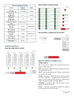
“Evap1”
– Evaporator 1: indicates the evaporator temperature
of the fi rst evaporator
“CTD”
– Compressor Time Delay: indicates remaining time in
compressor delay countdown
“PTD”
– Pump Time Delay: indicates remaining time in pump
countdown, when the count down starts the pump turns on
Indicator Box
– indicates if the unit has been called to run
(green means run, red means on standby)
Heat Call
– indicates if the master is calling units to run to meet
building demand (green means run, red means on standby)
“TempAvg”
– Tank Temperature Average: indicates the
average current tank temperature which comes from all of
the valid connected temperature probes averaged together
“TempSet”
– Tank Temperature Setpoint: indicates the
desired tank temperature to be maintained
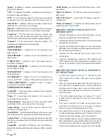
ALARM SCREEN
“HIGH PRESSURE 1”
– indicates if unit 1 has alarmed out on
high pressure
“LOW PRESSURE 1”
– indicates if unit 1 has alarmed out on
low pressure
“COND FLOW 1”
– indicates if unit 1 has alarmed out on
condenser water fl ow
“EVAP FLOW 1 / BLOWER 1”
– indicates if unit 1 has alarmed
out on evaporator fl ow
“M PROTECTION 1”
– indicates if unit 1 has alarmed out on
motor protection
“OIL PRESSURE 1”
– indicates if unit 1 has alarmed out on
oil pressure “ESTOP” – indicates if the Estop has been pressed
“TANK1 PROBE STATUS”
– indicates if tank 1’s probe is
connected and reading valid data
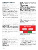
CONFIGURATION SCREEN
“Comp HRS”
– Compressor Hours: indicates the compressor
run time hours of each unit
“Pump %” -
Percentage of envelope sent to pump via
communication connection.
“Pump Staging”
- Percentage of pump envelope called
depending on how many heat pumps are running.
“Pump Testing”
- Used to hold system at a specific % for
setting Pump Staging values.
“Tank Diff Set”
– Tank Diff erential Setpoint: sets the minimum
tank temperature rise required to avoid calling another unit
“System Timer”
– System Timer: sets the maximum time that
the tank has to achieve the Tank Diff Set value to avoid calling
another unit
“TempDiff”
– Temperature Difference: sets the difference
below the setpoint where the master will give a call for members
to run
“SAVE”button
– Saves the“Tank Diff Set”and“System Timer”
parameters
“Master IP Address”
– IP Address used to connect panel to
BMS system
“Master IP Subnet”
– subnet mask for address range IP is
confi gured in
“Master IP Gateway”
– IP Address for internet router on site
used to connect to unit via VPN
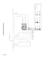
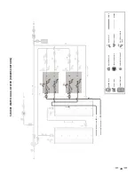
MASTER CONTROL PANEL SETUP TO
MEMBER UNITS
1. Hardwire all member units to individual power sources
rated for the equipment with disconnects
2.
Hardwire the “Master Control Panel” to a 120V power supply
through the junction box
3. Hardwire each temperature probe into the junction box
for the Master Control Panel and then permanently attach
them to their respective tanks
4. Connect all of the member units to the router in the
junction box
5. Under
the
confi guration screen press the “SEARCH FOR
UNITS” button to fi nd all of the connected members (give
the master controls 2 minutes to fi nd all of the member
units)
MASTER CONTROL UNIT CALL SEQUENCE
OF OPERATIONS
1. Set the “Tank Diff Set” value to 1°F and the “System
Timer” value to 300s (5min), then press save to update
the program
2. Once the master panel determines that there needs to
be a heat call it will determine the unit call order based
on; compressor run hours, alarm status, and unit number.
Then the master will call the unit in the fi rst unit in the run
order to turn on
3. If the tank temperature does not increase 1°F in 300
seconds than the second unit in the run order will be
called to run
4. The master controls will keep reevaluating these
conditions and calling units as necessary to achieve
the desired rise in the desired amount of time
5. If
you
fi nd that the units are not turning on fast enough
to meet building demand change the “System Timer” to a
smaller value in order to have units turn on quicker
6. If you fi nd that too many units are turning on and meeting
the building demand very quickly (almost in a manner of
short cycling) you should try increasing the “Tank Diff Set”
value so that additional units will only turn on as needed
Summary of Contents for AHPM-270
Page 2: ......
Page 10: ...6 Thermostatic Expansion Valve TXV Condenser Paddle Wheel Flow Sensor Accumulator Receiver...
Page 11: ...7 WATER TO WATER CYCLE...
Page 40: ...36 Service Log Issue Description Date Servicer...
Page 41: ...Service Log Issue Description Date Servicer 37...
Page 42: ...Notes 38...
Page 43: ......
Page 44: ......

