4
4. In order to expedite your request, please have full model
and serial number available for the technician.
5. Carefully consider your intended placement and location
for the HPWH. See Locating The Water Heater on page 9.
6. Installation and service of this HPWH requires ability
equivalent to that of a licensed tradesman or Qualifi ed Agency
in the fi eld involved. See Qualifi cations on page 3.
7. For installation in California the HPWH unit must be braced
or anchored to avoid falling or moving during an earthquake.
Instructions may be obtained from California Offi
ce of the State
Architect, 1102 Q Street, Suite 5100, Sacramento, CA 95811.
8. Ensure the power supply voltage and phase at the job site
matches the power requirements on the HPWH rating label
before installation begins. Energizing the HPWH with the wrong
voltage or phase will cause permanent damage to the unit.
PRINCIPLE OF OPERATION
The units covered by this Instruction Manual are commercial
modular water-to-water heat pump water heaters (HPWH).
Operation of the HPWH is similar to that of a package air
conditioning system. The primary diff erence in operation is that
the HPWH unit utilizes the heat removed from the conditioned
space to heat water where package air conditioning systems
discard this heat outdoors. Recovering and using this waste
heat increases the overall energy effi
ciency of the building.
THE REFRIGERATION CYCLE
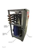
Refer to Figure 1 and the WATER TO WATER CYCLE on pages
5-7 for the location of components mentioned in this section.
Refrigerant is circulated through the refrigeration circuit by a
Compressor
. The refrigerant is a high temperature high pressure
gas when it leaves the compressor. Refrigerant fl ows from the
compressor through the
Hot Gas Line
to the
Condenser
.
The condenser is a refrigerant-to-water heat exchanger with
two circuits, refrigerant fl ows through one circuit and water
through the other. The high temperature refrigerant gas transfers
its heat to the water fl owing through the condenser. As the
refrigerant gas cools inside the condenser it changes state
(condenses) from a gas to a liquid. A customer provided Water
Pump circulates water through the condenser.
Refrigerant leaving the condenser is a medium temperature
high pressure liquid. It fl ows through the Liquid Line to the
Thermostatic Expansion Valve. The thermostatic expansion
valve (TXV ) regulates the flow of refrigerant into the
Evaporator. The evaporator is a single wall brazed plate source
water-to-refrigerant heat exchanger. The refrigerant changes
state (boils/evaporates) from a liquid state back into a gas (vapor)
in the evaporator.
The refrigerant fl ows out of the evaporator through the Suction
Line and into the Accumulator. The accumulator traps any
liquid refrigerant the evaporator is unable to vaporize during
low temperature operating conditions. The accumulator
prevents liquid refrigerant from entering the compressor
where it could damage internal components.
Low temperature, low pressure refrigerant gas (vapor) is drawn
out of the accumulator by the compressor. The compressor
increases the pressure and temperature of the refrigerant gas
circulating it to the condenser again where the refrigeration
cycle starts over or continues.
SOURCE WATER TEMPERATURE RANGE
The entering source water temperature operating range for
the HPWH is 40°F to 100°F (4°C to 38°C).
When the HPWH is operating properly the source water
temperature drop through the evaporator (heat exchanger)
will be approximately 8°F to 11°F (-13°C to -12°C).
WATER TEMPERATURE RANGE
The inlet (entering) water temperature operating range for
the HPWH is 40°F to 140°F (4°C to 60°C). The HPWH will heat
potable water up to
160°F
.
When the HPWH is operating properly the water temperature
rise through the condenser (heat exchanger) will be approximately
8°F to 12°F (4°C to 7°C).
REFRIGERANT CHARGE
The HPWH is factory-charged with R-134a refrigerant. The
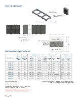
refrigerant charge is weighed in at the factory. See Table 9 on
page 25
.
It should not be necessary to add or remove refrigerant
during installation or start up.
EQUIPMENT DISPOSAL
This heat pump water heater contains R-134a refrigerant and
is regulated as a stationary refrigeration appliance under Section
608 of the Clean Air Act. Disposal of this unit must be performed
in accordance with the provisions in Section 608 of the Clean
Air Act and any state or local regulations that may also apply.
See Qualifi cations on page 3.
Summary of Contents for AHPM-270
Page 2: ......
Page 10: ...6 Thermostatic Expansion Valve TXV Condenser Paddle Wheel Flow Sensor Accumulator Receiver...
Page 11: ...7 WATER TO WATER CYCLE...
Page 40: ...36 Service Log Issue Description Date Servicer...
Page 41: ...Service Log Issue Description Date Servicer 37...
Page 42: ...Notes 38...
Page 43: ......
Page 44: ......


