TABLE 2
MODEL
VOLTS/PHASE/HZ
COMPRESSOR
BLOWER MOTOR PUMP (230 VAC 1Ø)*
MCA
MFS
RLA
LRA
MCC
FLA
HP
FLA
HP
AWH-35
208-230/1/60
18.60
100.00
29.00
3.60
1/2
0.88
1/8
28
45
AWH-
3
5
208-230/3/60
10.90
77.00
17.00
2.40
1/2
0.88
1/8
17
25
AWH-
3
5
460/3/60
5.40
39.00
8.50
1.20
1/2
0.88
1/8
9
12
AWH-55
208-230/1/60
27.90
175.00
43.50
5.30
3/4
0.88
1/8
42
60
AWH-55
208-230/3/60
19.90
115.00
31.00
3.00
3/4
0.88
1/8
29
45
AWH-55
460/3/60
8.70
63.00
13.50
1.50
3/4
0.88
1/8
13
20
AWH-75
208-230/3/60
24.00
196.00
37.50
3.60
1
0.88
1/8
35
50
AWH-75
460/3/60
11.50
100.00
18.00
1.80
1
0.88
1/8
17
25
AWH-100
208-230/3/60
28.20
225.00
44.00
3.60
1
0.88
1/8
40
60
AWH-100
460/3/60
14.10
114.00
22.00
1.80
1
0.88
1/8
20
30
AWH-115
208-230/3/60
35.30
239.00
55.00
3.60
1
1.00
1/6
49
80
AWH-115
460/3/60
17.90
125.00
28.00
1.80
1
1.00
1/6
25
40
AWH-140
208-230/3/60
48.10
300.00
75.00
4.80
1 1/2
2.50
1/2
68
110
AWH-140
460/3/60
21.80
150.00
34.00
2.40
1 1/2
2.50
1/2
31
50
AWH-170
208-230/3/60
52.60
340.00
82.00
6.20
2
2.50
1/2
75
125
AWH-170
460/3/60
25.60
173.00
40.00
3.10
2
2.50
1/2
37
60
*460 VAC models factory-equipped with step down transformer for 230 VAC pump
Abbreviations:
RLA = Running Load Amps;
LRA = Locked Rotor Amps;
MCC = Maximum Continuous Current;
FLA = Full Load Amps;
MCA = Minimum Circuit Ampacity;
MFS = Maximum Fuse Size
11
UNCONDITIONED SPACE
When installed in an unconditioned space ducting return (inlet)
air from an alternate location may be necessary to access an
adequate or greater source of heat for optimal efficiency. See
CLEARANCES
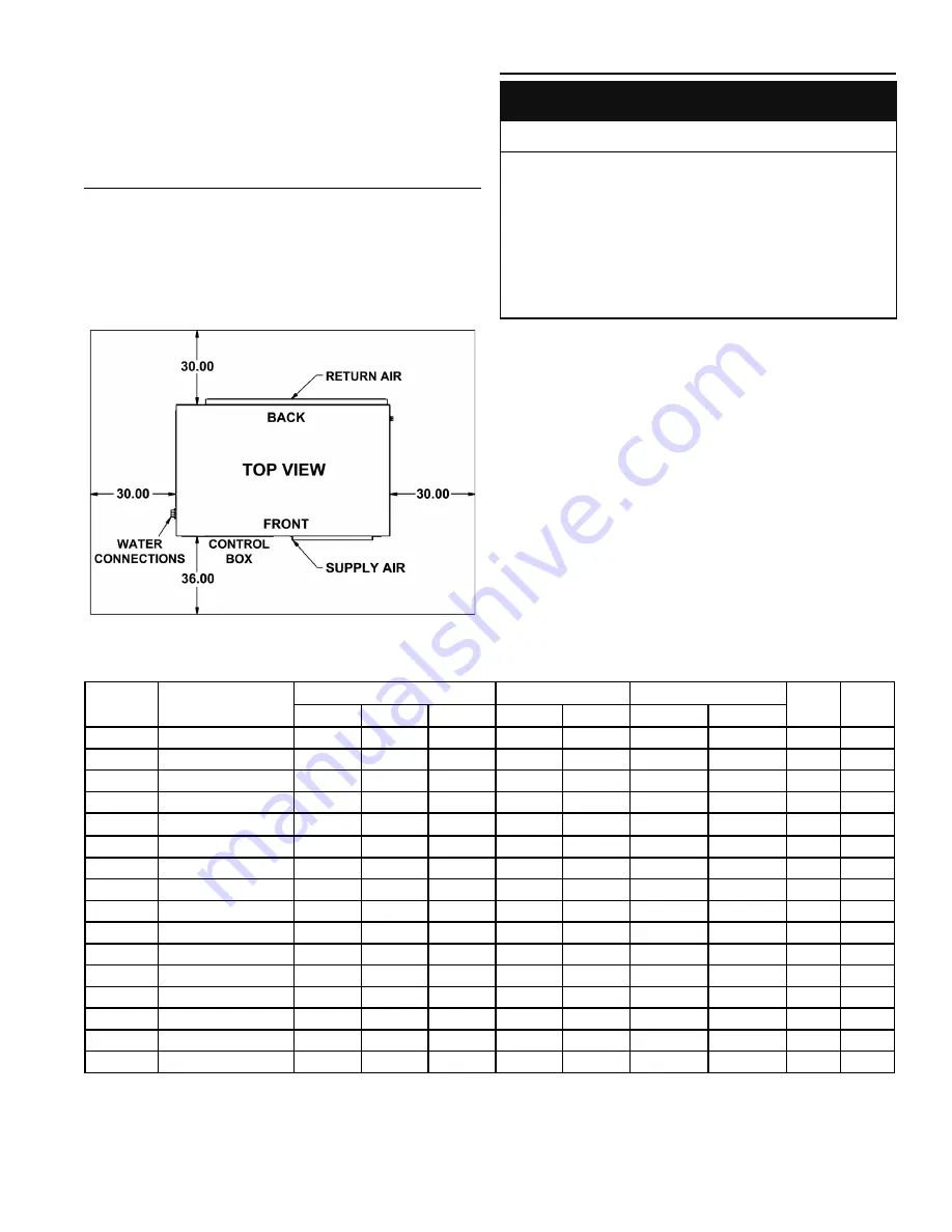
To ensure optimal performance a minimum of 30 inches clearance
is required from the back, left and right sides of the HPWH unit
and any wall obstruction. A minimum of 36 inches clearance on
the front of the unit for access to the control box. See Figure 3
When installed on an equipment pad the HPWH must be level
and elevated at least 6” above floor to avoid dust and debris and
permit connection of the condensate line and trap.
Figure 3
ELECTRICAL REQUIREMENTS
CORRECT POWER SUPPLY!
Ensure the power supply at the job site matches the
voltage and phase listed on the HPWH rating label
before connecting power to the HPWH unit.
•
Damage caused to the HPWH as the result of applying
the wrong voltage or phase is not covered under the
limited warranty.
•
Energizing the HPWH with the wrong voltage or phase
will cause permanent damage to the HPWH unit.
•
CAUTION
Ensure the power supply voltage and phase at the job site
matches the power supply ratings listed on the HPWH rating
label BEFORE INSTALLATION BEGINS.
The installation must conform with these instructions and the
local code authority having jurisdiction and the requirements
of the power company. In the absence of local codes, the
installation must comply with the current editions of the National
Electrical Code, ANSI/NFPA 70 or the Canadian Electrical Code
CSA C22.1.
Voltage applied to the HPWH should not vary more than +5% to
-10% of the voltage requirement listed on the HPWH rating label
for satisfactory operation.
VOLTAGE & AMPERAGE RATINGS
Summary of Contents for AWH-35
Page 2: ......
Page 32: ...UNIT WIRING DIAGRAMS FUSE SIZES 208 230 VAC SINGLE PHASE 60 HZ 32...
Page 33: ...UNIT WIRING DIAGRAMS FUSE SIZES 208 230 VAC THREE PHASE 60 HZ AWH 35 AWH 55 and AWH 75 only 33...
Page 34: ...UNIT WIRING DIAGRAMS FUSE SIZES 208 230 VAC THREE PHASE 60 HZ only 34...
Page 35: ...UNIT WIRING DIAGRAMS FUSE SIZES 460 VAC THREE PHASE 60 HZ 35...
Page 36: ...UNIT WIRING DIAGRAMS FUSE SIZES 460 VAC THREE PHASE 60 HZ only 36...


