background image

14

THE  WATER  HEATER  IS  EQUIPPED  WITH AN ADJUSTABLE 

THERMOSTAT  TO  CONTROL  WATER  TEMPERATURE.  HOT 

WATER  AT  TEMPERATURES  DESIRED  FOR  AUTOMATIC 

DISHWASHER AND  LAUNDRY  USE  CAN  CAUSE  SCALDS 

RESULTING IN SERIOUS PERSONAL INJURY AND/OR DEATH. 

THE TEMPERATURE AT WHICH INJURY OCCURS VARIES WITH 

THE PERSON’S AGE AND TIME OF EXPOSURE. THE SLOWER 

RESPONSE TIME OF CHILDREN , AGED OR DISABLED PERSONS 

INCREASES THE  HAZARD TO THEM.  NEVER ALLOW  SMALL 

CHILDREN TO USE A HOT WATER TAP, OR TO DRAW THEIR OWN 

BATH WATER.  NEVER LEAVE A CHILD OR DISABLED PERSON 

UNATTENDED IN A BATHTUB OR SHOWER.
It is recommended that lower water temperatures be used to avoid 

the risk of scalding. It is further recommended, in all cases, that the 

water temperature thermostats (See Figure 4) be set for the lowest 

temperature  which  satisfies  your  hot  water  needs. This  will  also 

provide the most energy efficient operation of the water heater. 
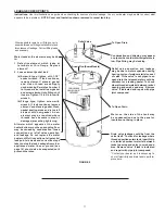
Figure  4  shows  the  approximate  time-to-burn  relationship  for 

normal  adult  skin. The  thermostats  on  your  water  heater  have  a 

linear  relationship  between  degrees  of  angular  rotation  and  the 

corresponding change in temperature.  Thus rotating the temperature 

adjustment indicator 30 angular degrees will result in a 10 degree 

Fahrenheit change in water temperature.

Water Temperature


°F (°C)

Time for 1st Degree Burn


(Less Severe Burns)

Time for Permanent Burns


2nd & 3rd Degree


(Most Severe Burns)

110 (43)

(normal shower temp.)

116 (47)

(pain threshold)

116 (47)

35 minutes

45 minutes

122 (50)

1 minute

5 minutes

131 (55)

5 seconds

25 seconds

140 (60)

2 seconds

5 seconds

149 (65)

1 second

2 seconds

154 (68)

instantaneous

1 second

(U.S. Government Memorandum, C.P.S.C., Peter L. Armstrong, Sept. 15, 1978)

FIGURE 4

TEMPERATURE ADJUSTMENT

The water heater is supplied with thermostats that may come from 
different manufactures and have different temperature indications 
as described below.

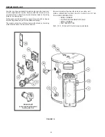
APCOM THERMOSTATS 

A-8 Circuit thermostats have three designated set points; LO, MED 

and HI. (See Figure 5).The approximate equivalent temperatures for 

these three settings are: LO = 140°F (60°C), MED = 160°F (71°C) and 

HI = 181°F (83°C). These thermostats are set from the factory at the 

LO 140°F (60°C) setting.  The over temperature device (ECO high 

limit) attached to each thermostat has a manual reset. The C-2 circuit 

thermostat is adjustable from approximately 130°F (54°C) to 170°F 

(77°C) (See Figure 6). These thermostats are set from the factory at 

approximately the 140°F (60°C) setting. The over temperature device 

(ECO high limit) attached to each thermostat has a manual reset.

        30A 120-250 VAC

             22A 277 VAC

        12.5A 480-600VAC

125 VA.PT.DTY. 120-480 VAC

MODEL WH10C

MED

40A 120-277 VAC

25A.480-600 VAC

  125VA.PT.DTY.

   120-480 VAC

APCOM

   INC


FIGURE 5 


FIGURE 6 

THERMODISC THERMOSTATS

A-8 circuit thermostats are adjustable from approximately 120°F 
(49°C) (lowest setting) to 181°F (83°C) (highest setting) (See Figure 
7)
. The C-2 circuit thermostat is adjustable from approximately 110°F 
(43°C) to 170°F (77°C) (See Figure 8). These thermostats are set 
from the factory at approximately the 140°F (60°C) setting. The over 
temperature device (ECO high limit) attached to each thermostat 
has a manual reset.


L1

L3

L4

T2

T4

L2

T1

THERM O DISC

89T

RESET

RESET

181°F

83°C

60°C

49°C

120°F

140°F


L1

L3

L4

T2

T4

L2

T1

THERM-O-DISC

RESET

170°F

140°F

110°F

RESET


FIGURE 7 


FIGURE 8 

NOTE: It is not necessary to adjust the upper thermostat for a dual 
element unit. However, if it is adjusted above the factory set point 
140°F (60°C) it is recommended that it not be set higher than the 
lower thermostat setting.

To change the temperature setting:
1.  DANGER: Turn off the heater electrical supply. Do not attempt 

to adjust thermostat with power on.

2.  Open  the  junction  box  door  (for  upper  thermostat  of  dual 

element water heater only) and/or remove the (lower) thermostat 

access panel. Do not remove the plastic personnel protectors 

covering the thermostats. The thermostat is factory pre-set at 

140°F (60°C). 

3.  Using a flat tip screwdriver, rotate the adjusting knob to the 

desired temperature setting.

4.  Replace  the  covers  and  access  panels,  and  turn  on  heater 

electrical supply.

TEMPERATURE REGULATION

Summary of Contents for BURKAY 102 Series

Page 1: ...L ELECTRIC WATER HEATERS Thank you for buying this energy efficient water heater We appreciate your confidence in our products MODELS DEL 6 10 15 20 Series 102 DEL 30 40 50 Series 110 DEN 30 40 52 66...

Page 2: ...ition to electrical testing skills when performing service ANSI Z223 1 2006 Sec 3 3 83 Qualified Agency Any individual firm corporation or company that either in person or through a representative is...

Page 3: ...unding conductor must be run with the circuit conductors and connected to the equipment grounding terminal or lead on the water heater HYDROGEN GAS FLAMMABLE Hydrogen gas can be produced in a hot wate...

Page 4: ...om National Fire Protection Association 1 Batterymarch Park Quincy MA 02269 The Canadian Electrical Code is available from the Canadian StandardsAssociation 8501 East Pleasant Valley Road Cleveland OH...

Page 5: ...element operation 4 1 gal x KW of one element for simultaneous element operation 4 1 gal x 2 3 KW of both elements For other rises multiply element KW as previously explained by 410 and divide by temp...

Page 6: ...6 APPROVALS MODEL AND RATING DEL 30 40 50 DEN 30 40 52 66 80 120 DEL 6 10 15 20 All models are listed by Underwriters Laboratories Inc...

Page 7: ...E CANADIAN ELECTRICAL CODE FOR PROPER INSTALLATION INSTALL IN ACCORDANCE WITH ALL LOCAL CODES INSTALL VACUUM RELIEF IN COLD WATER INLET LINE AS REQUIRED BY LOCAL CODES INSTALL SUITABLE DRAIN PANS UNDE...

Page 8: ...tions where leakage may result in property damage even with the use of a drain pan piped to a drain However unanticipated damage can be reduced or prevented by a leak detector or water shut off device...

Page 9: ...ble and are to be set at a maximum of 125 degree F Consult a qualified installer or service agency Follow all manufacturer s Instructions for installation of these valves Before changing the factory s...

Page 10: ...e location Shall not have any valve or other obstruction between the relief valve and the drain The temperature pressure relief valve must be manually operated at least once a year Caution should be t...

Page 11: ...ingle element heater equipped with a high limit control single phase power input 2 Four wire A 8 circuit for dual element heater equipped with two high limit controls single phase or three phase power...

Page 12: ...12 Figure 3 WIRING DIAGRAMS C 2 CIRCUIT FOR SINGLE ELEMENT HEATERS EQUIPPED WITH HIGH LIMIT CONTROL A 8 CIRCUIT FOR DUAL ELEMENT HEATER FACTORY WIRED FIELD WIRING WHITE FOR 120V 277V...

Page 13: ...ness Also check connections on top and or sides of heater Repair water leaks and tighten electrical connections as necessary 3 Depress the red manual reset button on each Thermostat ECO combination co...

Page 14: ...HI See Figure 5 The approximate equivalent temperatures for these three settings are LO 140 F 60 C MED 160 F 71 C and HI 181 F 83 C These thermostats are set from the factory at the LO 140 F 60 C set...

Page 15: ...y the anode rod This does not affect water s taste or color The rod must be maintained to keep tank in operating condition Anode deterioration depends on water conductivity not necessarily water condi...

Page 16: ...ating The sounds are normal however the tank bottom and elements should be cleaned See the Maintenance section of this manual WATER LEAKAGE IS SUSPECTED Refer to Leakage Checkpoint on the following pa...

Page 17: ...ary to shut off electricity and drain tank to perform procedure Water leaks at the elements may be due to 1 Defective element which leaks at terminals or thru flange Replace element 2 Loose element ga...

Page 18: ...improper gas supply line sizing gas type venting connections combustion air voltage wiring or fusing Failure to follow applicable codes Failure to follow printed instructions Abuse misuse accident fi...

Page 19: ...19 NOTES...

Page 20: ...s will be shipped at prevailing prices and you will be billed accordingly The model number of your Water Heater will be found on the rating plated located above the lower access panel Be sure to provi...

Page 21: ...nstruction Manual 322055 0 322055 0 322055 0 322055 0 10 Personnel Protector 9003914015 9003914015 9003914015 9003914015 11 Pipe Nipple 194130 194130 3 194130 3 194130 3 12 Plate Knockout 43293 1 4329...

Page 22: ...2857015 9002857015 9002857015 9002857015 9002857015 9002857015 9002857015 7 Thermostat Bracket each 9003898215 9003898215 9003898215 9003898215 9003898215 9003898215 9003898215 9003898215 9003898215 8...

Page 23: ...4005 9002875005 TABLE 7 INCOLOY SHEATH ELEMENT AND WATTAGE CHART FOR SMR P72 K W ELEMENT WATTAGE 120 V 208 V 240 V 277 V 480 V PART NO PART NO PART NO PART NO PART NO 1 5 1500 W 9004279005 9004283005...

Page 24: ...24 500 Tennessee Waltz Parkway Ashland City TN 37015 Technical Support 800 527 1953 Parts 800 433 2545 www hotwater com Copyright 2015 A O Smith All rights reserved...

Reviews: