50
50
50
50
50
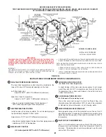
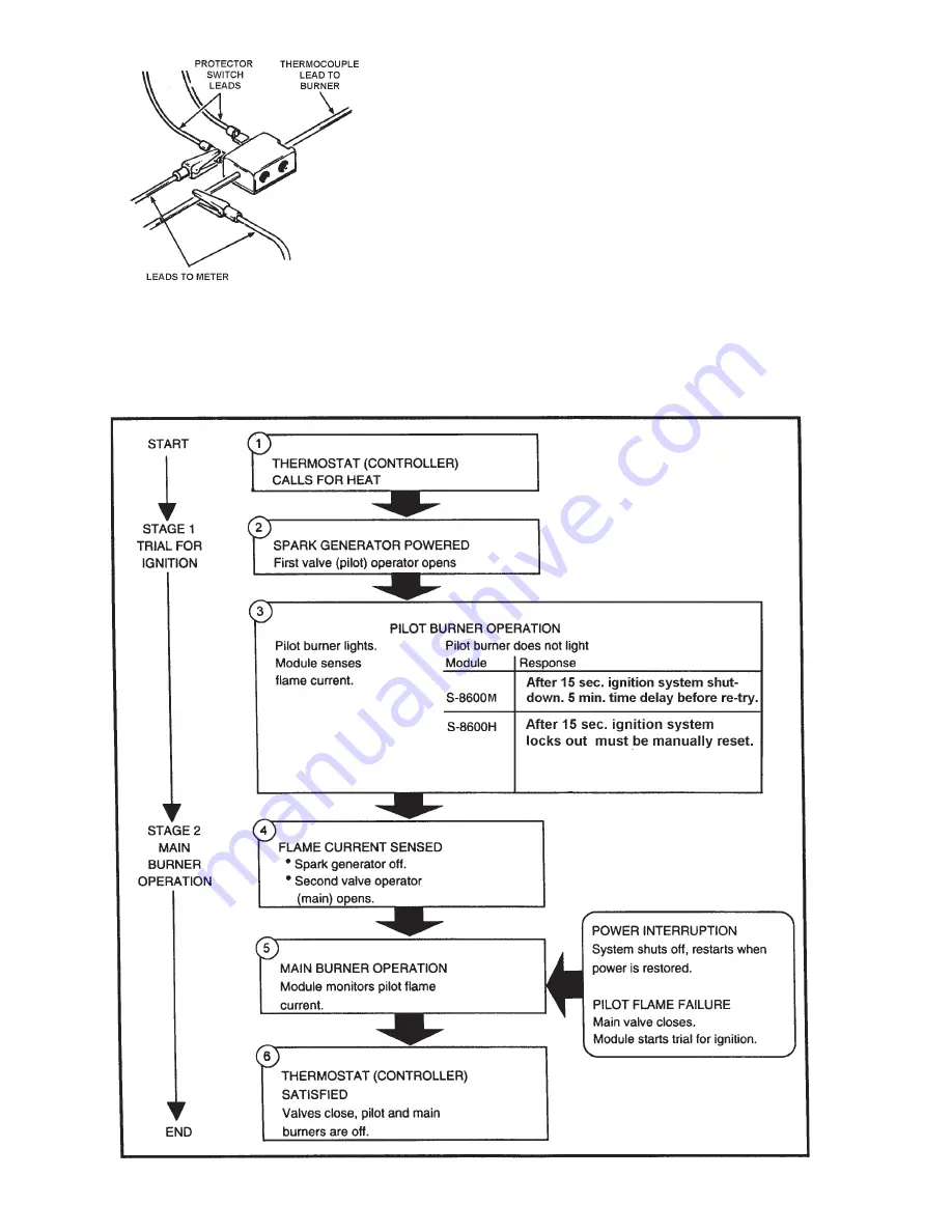
FIGURE 43D
The purpose of checking the current ahead and after the protector
switch is to measure the millivolt drop across the contacts. This
drop should be between 4 and 6 millivolts.
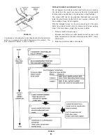
PROTECTOR SWITCH CONTINUITY TEST
Do not depress the protector switch reset button prior to testing.
The leads from the switch are removed from the thermocouple
function block and attached to the leads from a test flashlight.
The model N22T test kit (combination flashlight and continuity
tester) is manufactured by the RAY-O-Vac Company, Madison, WI
and available through local suppliers.
With the flashlight turned on, the lamp should light. If the lamp
lights, the protector switch circuit is closed and in proper working
order. If the lamp does not light, the reasons could be:
1.
Protector switch contacts open.
•
Depress reset button on switch (switch cannot be reset until
water temperature in the boiler coils drop below 200°F). Lamp
should light.
2.
Defective protector switch or bad leads.
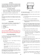
FIGURE 44


