25
Adjustment, if required, is performed as follows:
1. Set primary system temperature control dial (thermostat) at
lowest setting so that boiler will not call for heat.
2. Attach a pressure gauge to the tapping in the control string
elbow.
3. Reset primary system temperature control dial (thermostat)
to highest setting. Main burner will now ignite.
4. With main burner firing, adjust pressure, if necessary, by
turning pressure regulator adjusting screw with a screwdriver.
• Clockwise to increase pressure.
• Counterclockwise to decrease pressure.
5. Set primary system temperature control dial (thermostat) to
lowest setting.
6. Remove pressure gauge and replace sealing plug.
7. Set primary system temperature control dial (thermostat) to
desired setting.
Do not increase gas pressure above that specified on the rating
plate, as overfiring will result in damage to the boiler, as well as
increased risk of fire, sooting and asphyxiation.
If gas pressure regulator cannot be adjusted to correct pressure
with sufficient gas pressure at the valve, replace with new gas
control valve.
GAS MANIFOLD PRESSURE REGULATORS
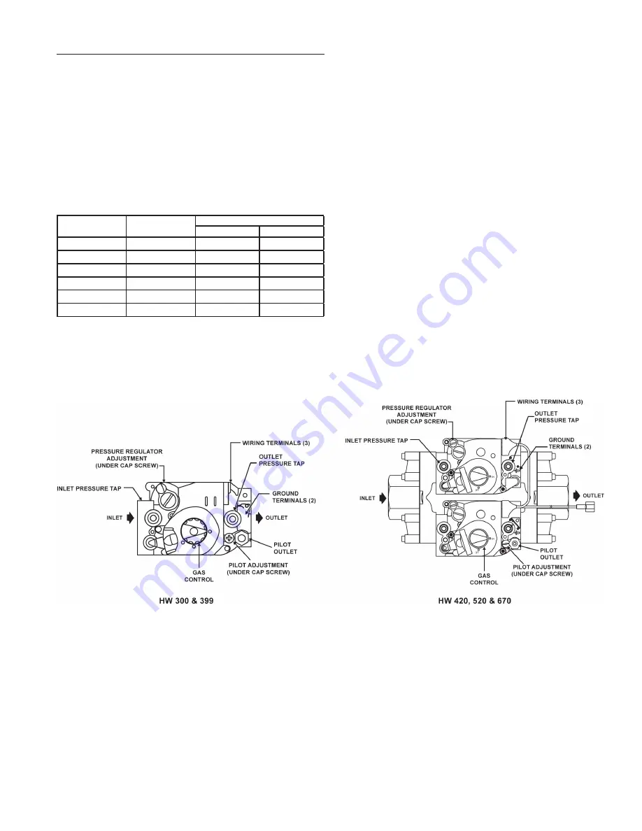
The gas manifold pressure regulator is included in the
combination gas control valve, Figure 18, and is set to operate
on the gas specified on the boiler model and rating plate.
Periodically check main burner, Figure 19 on Page 26, and
pilot flame, Figure 20 on Page 27, for proper operation. This
should be checked every six months.
Do not subject the gas control valve to inlet gas pressures of
more than 14" W.C. (1/2 P.S.I.). If higher gas pressures are
encountered, a service regulator is necessary.
Model
Number
Rated
Input
Manifold Pressure
Natural
Propane
HW-300
300,000
3.5
10.0
HW-399
399,000
3.5
10.0
HW-420
420,000
3.5
10.0
HW-520
520,000
3.5
10.0
HW-670 Nat.
660,000
3.5
HW-670 Prop.
670,000
10.0
TABLE 15.
CORRECT MANIFOLD PRESSURE FOR FULL BOILER
INPUT (IN INCHES OF WATER COLUMN)
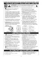
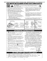
FIGURE 18. GAS CONTROL VALVES (NATURAL GAS & PROPANE)


