42
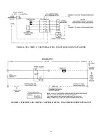
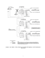
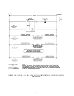
The electrical connections must be made so that the circulating
pump will operate before the gas control valve opens. At no time
may the controlling system allow the burner to fire when there is
no water flow through the boilers.
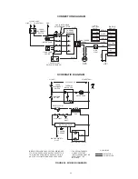
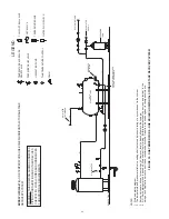
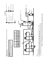
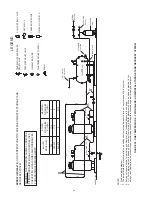
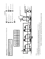
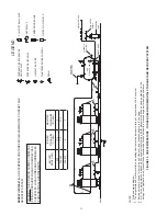
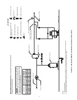
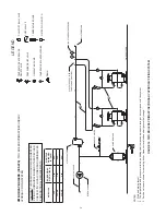
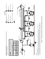
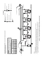
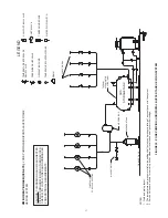
Refer to the diagram in Figure 24 on Pages 43 for proper wiring
sequence with conventional single boiler installations.
The thermal balancer shown is factory included by A. O. Smith.
This device serves as a pump shutdown delay switch to balance
the rising boiler water temperature to system temperature
before the pump stops. Overshooting of boiler temperature is
prevented and stack loss after shutdown is negligible.
If any of the original wire, as supplied with the boiler, must
be replaced, it must be replaced with type 105
0
c wire or its
equivalent, except for the flame sensor and ignition cable
which are 250
0
c and wires connected to the coil protector
which are 200
0
c.
WIRING
WIRING CONNECTIONS
CONVENTIONAL INSTALLATIONS
All electrical work must be installed in accordance with current
editions National Electrical Code, ANSI/NFPA 70 and/or the
Canadian Electrical Code, PART 1, CSA C22.1, Electrical Code
and must conform to local regulations.
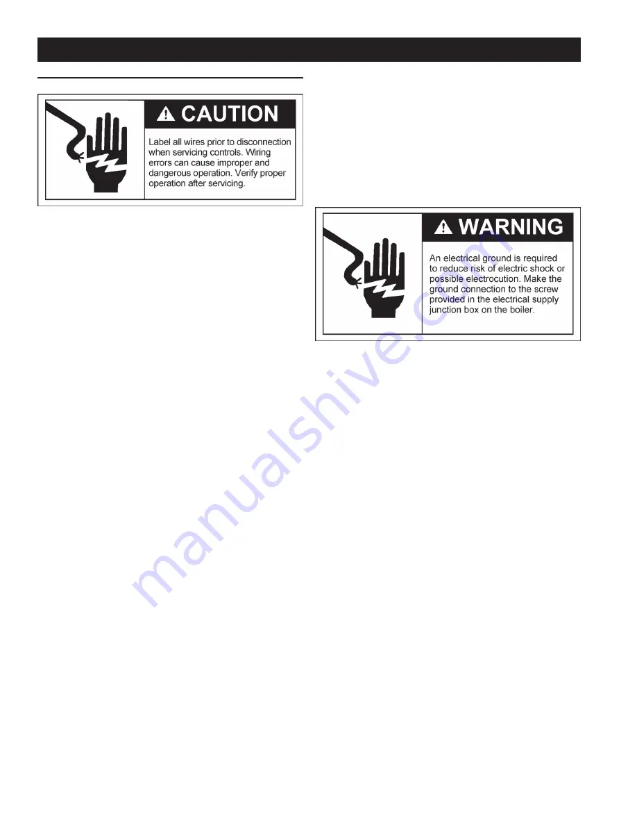
The boiler, when installed, must be electrically bonded to ground
in accordance with the requirements of the authority having
jurisdiction or, in the absence of such requirements, with the
current editions National Electrical Code, ANSI/NFPA 70 and/
or the Canadian Electrical Code Part 1, CSA C22.1, Electrical
Code.
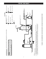
Strict adherence to piping and wiring diagrams is required to
prevent constant pump operation when system temperature
control is satisfied. Otherwise the warranty is void as stipulated
in the limited warranty on the instructions manual.

