background image

 Installation and Service Manual Epsilon-Series 

13

-  Should  you  wish  to  achieve  the  required  water  quality  by  using  chemical  addi

-

tives, then this is your own responsibility. The warranty on the product delivered by 


A.O. Smith expires, if the water quality does not meet A.O. Smith's specifications or 

the chemical additives have not been approved by A.O. Smith.

-  On installation and during additions or changes at a later stage, A.O. Smith recom-

mends to keep a record of the type of water used, its quality at the time, and if ap-

plicable, which additives and quantities were added.

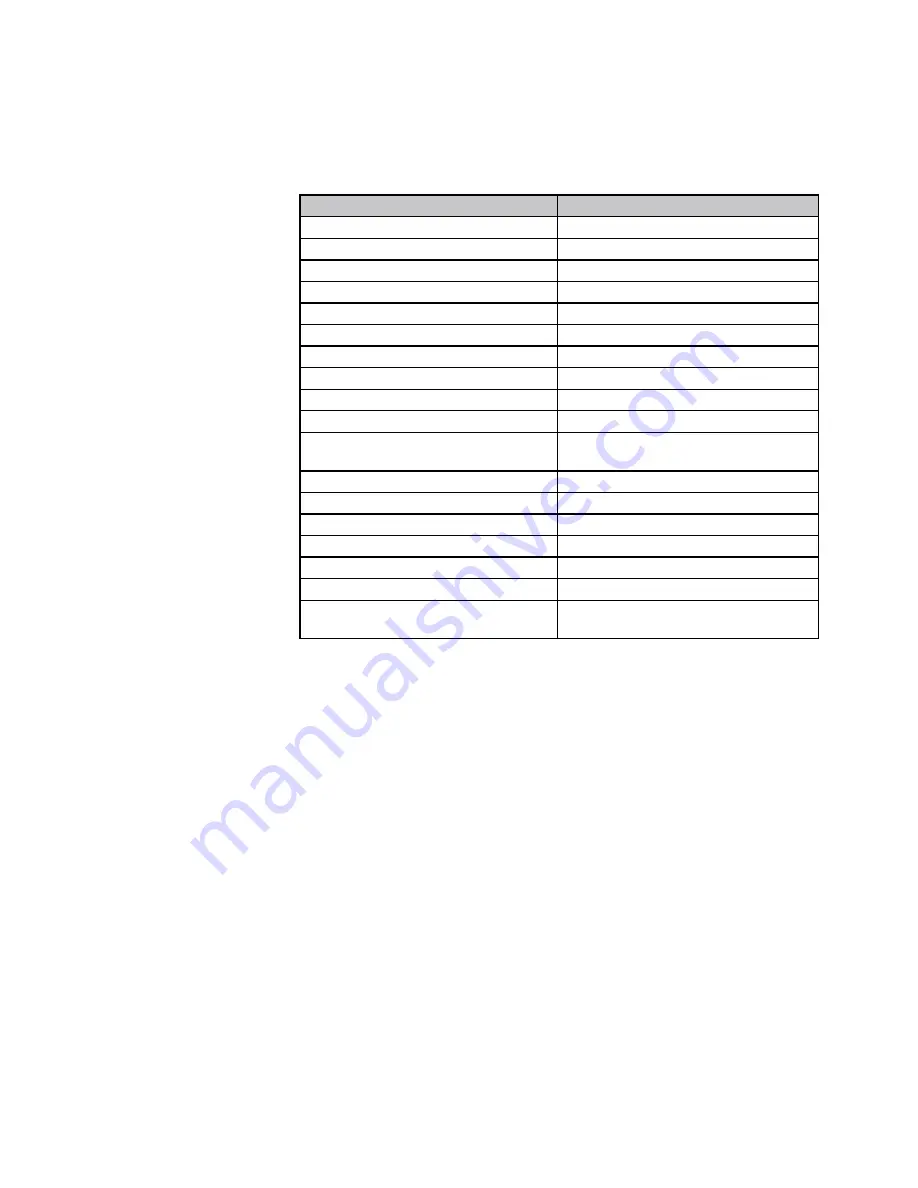
Parameter

Value

Water type

Potable water

Softened water

6.0-8.5

pH

6.0-8.5

Conductivity (at 20°C in µS/cm)

Max. 2500

Iron (ppm)

Max. 0.2

Hardness (°dH)

Installation volume/capacity 1-7

<20 l/kW

1-12

Installation volume/capacity

Refer to Additives Attachment

>=20 l/kW

1-7

Oxygen

No oxygen diffusion allowed during ope

-

ration.

Max. 5% filling water addition annually

Refer to Additives Attachment

Corrosion inhibitors

Refer to Additives Attachment

pH increasing or lowering agents

Refer to Additives Attachment

Anti-freeze additives

Refer to Additives Attachment

Other chemical additives

Refer to Additives Attachment

Solid substances

Not allowed

Residues of processing water not for-

ming part of the drinking water

Not allowed


table 6.3.a

Water type definition:

Potable water:  

Tap water compliant with the European drinking water guideline:  


98/83/EG dated 3 November 1998.

Softened water:   Water with partly de-ionised calcium and magnesium. 

Demi-water:  

Virtually completely demineralised water (very low conductivity)  

Distilled water:  

Water no longer containing minerals.

Summary of Contents for Epsilon EB-40

Page 1: ...me Light Commercial High Efficiency Condensing Boiler EB 40 50 Epsilon Installation and Service Manual These instructions should be retained by user XX XX XXX XX XX Changes reserved E O E 8G 51 90 04...

Page 2: ...c venting program 3 4 5 6 7 8 9 A Water pressure is to low 1 0 bar fla shing FILL will alternate with indication of water pressure boiler power of 50 is possible The installation needs to be topped up...

Page 3: ...ntral heating system 26 10 2 Adjustments 27 10 3 Activating factory settings green key function 29 11 Isolating the boiler 30 12 Commissioning 30 12 1 Checking for contamination 31 12 2 Checking the O...

Page 4: ...hese instructions thoroughly well in advance of installation Separate instructions for use are supplied with the boiler for users of A O Smith central heating boilers A O Smith is not liable for the c...

Page 5: ...ng panel 10 Control Tower CMS 11 water filter return CH 12 circulation pump 13 flue gas discharge 14 combustion air supply T1 flow sensor T2 return sensor P1 water pressure sensor Epsilon EB 40 figure...

Page 6: ...A O Smith Epsilon boiler is a certified appliance and must not be modified or installed in any way contrary to this Installation Manual Manufacturers instructions must not be taken in any way as overr...

Page 7: ...ce the housing and secure it with the screw behind the door at the front of the casing The following safety symbols may be encountered in these installation instructions and on the unit This symbol in...

Page 8: ...he boiler is drained through an internal siphon The boiler is provided with an intelligent control system CMS Control Management System The boiler anticipates the heat demand of the central heating sy...

Page 9: ...bracket and the enclosed fixing equipment The wall must be flat and of sufficient strength in order to be able to carry the boiler weight with its water content Above the boiler there must be at least...

Page 10: ...ation before connecting it to the unit 6 1 Central heating system Connect the central heating system according to the actual regulations The boiler pipes can be connected to the installation by means...

Page 11: ...s pump switches at the same times as the boiler pump The maximum absorbed current consumption of the external circulation pump may be 230 W 1 Amp The extra external pump must be selected according the...

Page 12: ...thout approval the warranty becomes invalid Installation The use of groundwater demi water and distilled water is prohibited on the next page you will find an explanation of these definitions If the d...

Page 13: ...dH Installation volume capacity 1 7 20 l kW 1 12 Installation volume capacity Refer to Additives Attachment 20 l kW 1 7 Oxygen No oxygen diffusion allowed during ope ration Max 5 filling water additi...

Page 14: ...lation valve can be screwed United Kingdom The gas supply must comply to the current Gas Safety Installation Use Regulations Ireland Irish standard 813 Domestic gas installations The connection to the...

Page 15: ...towards the outlet and take the shortest possible route Support the pipe at least every 50 cm for near horizontal sections and 1 metre for vertical sections External pipework The pipework should be ke...

Page 16: ...ger of freezing Before putting the boiler into operation fill the syphon with 600 ml of water A Condensate from boiler syphon trap B Sink with internal overflow C 25mm dia Plastic condensate pipe D Ex...

Page 17: ...nstallation must comply with the current regulation requirements IG UP 10 and BS 715 Ireland Irish standard is 813 section 9 10 1 Open boiler Room sealed system SS P SS P P SS P Open boiler en roomsea...

Page 18: ...on of 2x 80mm In this case a conversion kit concentric to parallel should be ordered Art nr 0310373 S A 1 Push the 2 clips slightly outwards B 2 Pull the concentric adaptor out of the boiler 3 Press t...

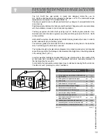
Page 19: ...at the terminal is reduced The terminal should be located where dispersal of combustion products is not impeded and with due regard for the damage or discolouration that might occur to building produ...

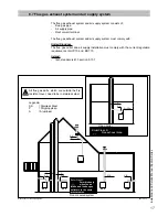
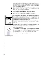
Page 20: ...the outlet system The chances of icicles forming on the roof outlet is minimised by causing the condensation water to run back towards the appliance In the case of horizontal outlets the inlet system...

Page 21: ...imum straight length 80 18 Maximum straight length 100 39 87 bend resistance length 1 4 87 bend resistance length 2 1 45 bend resistance length 0 9 45 bend resistance length 2 EB 50 Maximum straight l...

Page 22: ...The bus room thermostat and controls must be connected to their allocated connections All other types or makes of room thermostats or controls which are used must have a Volt free contact When using a...

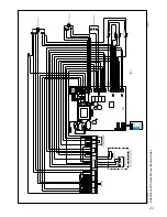
Page 23: ...Installation and Service Manual Epsilon Series 23 electrical diagram figure 7 b...

Page 24: ...te to the Technical read out and vice versa Press 5 sec on the STEP key When the system has been filled the automatic venting program starts when a program has been selected by pressing the key for Ce...

Page 25: ...trieved and pages per chapter can be retrieved After pressing for 5 seconds it switches from the Good state to technical read out and vice versa Reset key After briefly pressing for unlocking errors e...

Page 26: ...Activate the functions in use heating DHW and or pump 13 If A xx appears on the display wait for 17 minutes 14 Check the water pressure and if necessary top it up to 1 5 to 1 7 bar 15 Close the fillin...

Page 27: ...ecified in the current Gas Safety Regulations The boiler does not require adjustment of the burner pressure and air quantity because it is self adjusting and is factory set at the correct value 10 1 C...

Page 28: ...eters INFO Information chapter no adjustments possible SERV Service chapter ERRO Error chapter no adjustments possible The content of the chapters is described on the following pages Press briefly the...

Page 29: ...to 5 C 14 5 gradient speed 0 15 15 0 booster after night reduction no 00 yes 01 23 3 C Frost Temperature 20 to 10 C 27 0 C Min flow temperature 0 to 70 C 31 63 C Cylinder temperature with external cy...

Page 30: ...tion status boiler 3 C flow water temperature T1 4 C return water temperature T2 5 kW load 6 pump capacity heating line adjustments Parameter Step 6 and 7 graph 10 2 a outside temperature in C flow wa...

Page 31: ...s to be removed The casing is locked with a screw behind the door on the front and the top of the casing is hooked behind a locking edge After removing this screw the casing must be lifted at the bott...

Page 32: ...m the code code blinks 1 x Press the MODE key until SERV is shown Press the STEP key until 2 is shown alternately 2 and OFF will be shown Undo the top test nipple on the gas valve fig 12 1 a Connect t...

Page 33: ...will burn on full load value on display in kW Natural gas Propane O2 percentage at full load 4 7 1 2 0 8 5 1 1 2 0 7 CO2 percentage at full load 9 0 0 4 0 6 10 3 0 4 0 8 Let the O2 meter do its measu...

Page 34: ...the casing and remove it towards the front The air box Remove the transparant air box see fig 12 3 b Clean the box with a cloth with a simple non abrasive cleaning agent The fan unit and burner casset...

Page 35: ...onisation current has to be greater than 4 A at full capacity If the viewing glass is damaged the complete electrode must be replaced Replacement goes as follows Remove the electrical connections of t...

Page 36: ...Clean the condensate tray with water and a hard brush Check the condensate tray on leaks Step 3 Refitting is done in reverse order Note that all gaskets seals completely Make sure that during refitti...

Page 37: ...the system and to the building if the system does not remain operative during frost conditions Please ensure that if you are absent during a period of frost the central heating system remains in opera...

Page 38: ...e minimum or maximum power Block 67 A T has been detected between flow and return sensor whereas the burner is not in operation After the T has disappeared the block will disappear Block 80 Maximum fl...

Page 39: ...in articles 1 and 2 will apply solely under the following conditions a The central heating boiler is installed under strict adherence to A O Smith Water Heaters installation instructions for the spec...

Page 40: ...Shipping labor installation and any other costs associated with the replacement will not be accepted by A O Smith Water Heaters Replaced parts can only be claimed atA O Smith Water Heaters if they are...

Page 41: ...PMS Water pressure min max bar 1 3 1 3 Flow temperature max C 85 85 Pump type UPM2 20 70 20 70 Available pump height CH kPa 20 Low velocity header required CE product identification number PIN Techni...

Page 42: ...nopropyleneglycol propane 1 2 diol inhibitors 50 w w Anti freeze Sentinel X500 Monopropyleneglycol inhibitors Kiwa certified 20 50 w w Anti freeze Fernox Alphi 11 Monopropyleneglycol inhibitors Kiwa c...

Page 43: ...mm 65 65 H Left side flow pipe mm 185 185 J Left side return pipe mm 285 445 K Left side condensate pipe mm 370 530 P Pipe length of g mm 18 18 Q Pipe length of c mm 40 40 R Pipe length of a r mm 60...

Page 44: ...50 Concentric flue system mm 80 125 80 125 Parallel flue system mm 2x 80 2x 80 g Gas pipe 1 2 Rp 3 4 Rp a Flow pipe mm 28 35 r Return pipe mm 28 35 c Condensate pipe mm 24 24 Epsilon connection diamet...

Page 45: ...A0 Connection terminal Epsilon boiler A1 Room thermostat A4 Outside sensor tra Thermostatic radiator valve BP Automatic by pass Use alway a by pass in combination with thermostatic radiator valves Ann...

Page 46: ...allation with underfloor heating zone A Boiler A0 Connection terminal Epsilon boiler A4 Outside sensor A9 Zone controller A10 Connection terminal zone controller built in C Direct zone C6 Pump direct...

Page 47: ...2012 EN60335 2 12 2006 EN60335 2 102 2010 EN60335 1 2011 Boiler Efficiency Directive 92 42 EEC EN677 1998 Low Voltage Directive 2006 95 EG EN60335 2 102 2010 EN60335 1 2002 EMC Directive 2004 108 EG E...

Page 48: ...A O Smith UK Unit B8 Amstrong Mall Southwood Business Park Farnborough Hampshire GU14 0NR www aosmith co uk A O Smith Water Heaters is a trading name of Advance Services Sales Ltd Reg your installer...

Reviews: