24VOLT
I
'2
'
2
'
2
2
2
'
2
2
2
0
5
5
5
5
5
6
I
1
I
0
LI
AC
I
THERMAL
4 2 4 JUNCTION
BOX
WITHTERMINAL
STRIP
IOPTIONAU
A. 0,
(SEE
FIGURE
5
5
5
5
5
5
W EWERMOSTATS
4 8
4 8
4 -
S
4 .
4 6
4 6
4 8
4 5
4 8
4 5
4 5
4 5
3
1
3
1
3
1
3
3
1
3
40VATRANSFORMER
TOHANDLE
UPTO
.
8 ZONEVALVES
ZONE
VALVES
(w-RTYPE
1311.
MODEL
AA44E4
ORHIGHER
THAN41
T
T
w.a
809-A
1
2
L
L
RELAY
CIRCUl.ATING
•)
o
0
u
PUMP
120V
YELLOW
L2
..
BLACK
INEUTHAL)
NCER
REO
WHITE
(PUMP
OEt.AY)
M H
.
NO. 9920)
ENTRY
TERMINALS
PT4TA.=r
4)
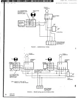
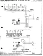
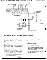
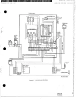
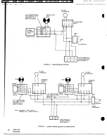
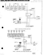
FIGuRE 9 - ZoNED SYSTEM - WHITE-RODGER5 3 WIRE ZONE YALVES
CLEANING
AND
FLUSHING
INSTRUCTIONS
When
completed,
the
hydronic
system
should
be
1.
Mix
1/2
gallon
of A.
O.
Smith
blydro-Prep
®
internally
cleaned
and
flushed
to
remove
contami-
hydronic
system
conditioner
with
three
quarts
nants
that
may
have
accumulated
during
installa-
of
warm
water.
tlon.
!
2.
Add
the
solution
to
the
system
using
either
Failure
to
do
so
can
produce
acid
concentrations
of
the
following
methods:
that
become
corrosive,
cause
gases
to
form
that
block
water
circulation
or
lead
to
formation
of
With
an
acid
pump
or
hand
pump
deposits
on
the
boiler
surfaces,
any
of
which
could
result
in
damage
to
the
system
and
cir-
a
Open
boiler
drain
valve
and
remove
an
culator.
amount
of
water
approximately
equal
to
the
volume
of
cleaning
solution
to
be
To
assure
system
cleanliness
and
long
life,
A.
O.
added.
Close
drain
valve.
Smith
*Hydro-Prep®
hydronic
system
conditioner
is
furnished
with
the
boiler.
After
making
'certain
•
Connect
pump
to
boiler
drain
valve,
Open
the
completed
installation
does
not
leak,
shut
off
drain
valve
and
pump
mixture
from
con-
the
cold
water
supply
and
proceed
as
follows:
tainer
into
the
system.
*AVAILA BLE IN QUARTS (PART NO. 97091) OR HALF GALLONS
•
Close
drain
valve
and
disconnect
pump.
(PART NO. 97092) FROM YOUR NEAREST A. O. SMITH CORP.
PRODUCT SERVICE DIVISION BRANCH.
12
AOS
112
Roenbeck
FILED: NEW YORK COUNTY CLERK 02/20/2018 10:20 AM
INDEX NO. 190311/2015
NYSCEF DOC. NO. 337
RECEIVED NYSCEF: 02/20/2018


