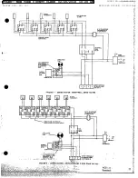
I
SA
PA
:I
ERST
SWITCH
MANUAL
Through
pressure
relief
valve
opening
4.
Operate
the
system
for
a minimum
of
1 hour
(to
a maximum
of
24
hours).
As
noted
above,
•
Close
system
inlet
and
outlet
valves
at
the
system
pressure
and
temperature
must
be
boiler.
such
that
the
water
does
not
boll.
e
Relieve
pressure
flam
boiler
and
remove
pressure
relief
valve
from
air
purger.
5.
SYSTEM
MUST
NOW
BE
DRAINED
AND
FLUSHED.
•
Remove
an
amount
of
water
from
the
sys-
tem
approximately
equal
to
the
volume
of
^
.
Close
the
manual
gas
shutoff
valve
to
cleaning
solution
tp
be
added.
turn
off
the
burner.
This
will
allow
the
circulator
to
continue
operating
during
.
Add
the
cleaning
solution
to
the
system
the
flushing
procedure.
through
the
relief
valve
opening.
Replace
relief
valve.
.
Open'
the
cold
water
supply
to
the
sys-
tem.
.
Open
system
inlet
and
outlet
valves
at
boiler.
*
Connect
a
hose
to
the
boiler
drain
valve,
.
allow
cleaning
solution
to
flow
to
drairt.
3.
Pressurize
the
system.
If
necessary
, open
the
cold
water
supply
alve
and
add
pressure
.
All
cleaner
should
be
removed
after
15
to
to
the
system
so
that
the
water
does
not
boil
20
minutes
of flushing.
during
the
cleaning
process.
OPERATING
INSTRUCTIONS
LIGHTING
INSTRUCTIONS
6
b"
I
sura
120V. SOHz
CAUTION:
Make
sure
heater
is
filled
with
water
TONexreANE
before
lighting
pilot.
The
main
(man-
J'2SED
•
PUMP
ual)
gas
shutoff
valve
and
pilot
ad-
___ay
Eu.OW
____
justing
valve,
located
near
main
an
__....__
_____
burner,
should
be
closed
for
at
least
RM
WH E
TON
U EPO
Lt
5
minutes.
SYSTEM
OPERATING
CONTROL
Do
not
attempt
to
light
pilot
if gas
odor
is
present.
Light
the
unit
in
accordance
with
the
instructions
on
the
Lighting
and
Operat|ng
plate
fastened
to
cE
the
boiler.
.
,
NO
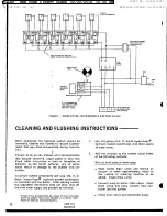
SAFETY I
.TRANSFORMER
TAANSPORMER
(24V)
P1LO
TO
Et1
I
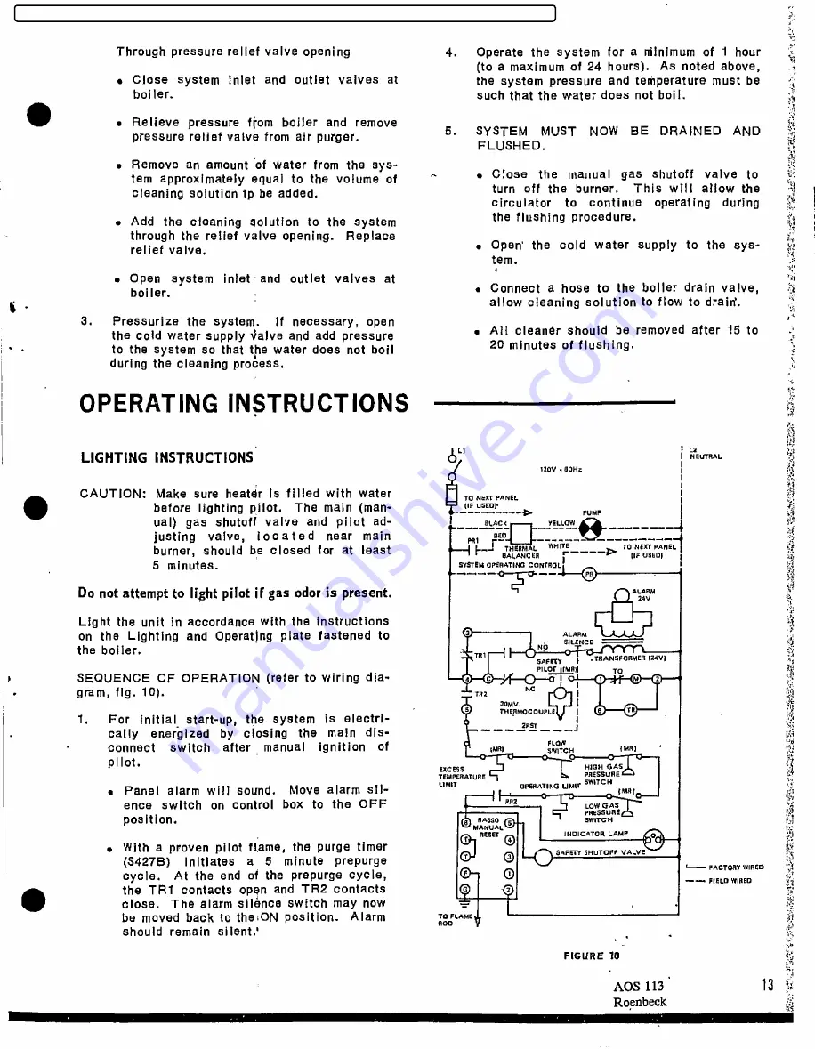
SEQUENCE
OF
OPERATION
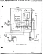
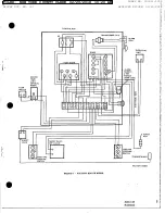
(refer
to
wiring
dia-
4
c
I
I
M
2
.
gram,
fig.
10).
TR2
I
30MV.
I
$
THERMOCOUPLE]
g
TR
1.
For
initial
start-up,
the
system
is
electri-
cally
energized
by
closing
the
main
dis-
connect
switch
after
manual
ignition
of
imm
cH
(MR
pilot.
EXCESS
HIGHGAS
TEMPERATURE
PRESSURE
e
Panel
alarm
will
sound.
Move
alarm
sil-
*
.
°""4'NG
IJMIT
IMAI
ence
switch
on
control
box
to
the
OFF
PR2
LOW
GAS
•
PRESSURE
position.
RA6SO
SWITCH
~
S
Q4
INDICATOR
LAMP
O
.
With
a proven
pilot
flame,
the
purge
timer
SAFETY
SHUTOFF
VALVE
(3427B)
initiates
a
5
minute
prepurge
L---- FACTORY
WIRED
cycle.
At
the
end
of
the
prepurge
cycle,
Q
--
FIELD
WillED
the
TR1
contacts
open
and
TR2
contacts
2
y
close.
The
alarm
silence
switch
may
now
.--
be
moved
back
to
theiON
position.
Alarm
TORAME
should
remain
silent.'
FlGURE
10
AOS
113
13
9
Roenbeck
FILED: NEW YORK COUNTY CLERK 02/20/2018 10:20 AM
INDEX NO. 190311/2015
NYSCEF DOC. NO. 337
RECEIVED NYSCEF: 02/20/2018


