I
I
man.'
~
~
~ L
m
& I' l(5
4
I
~ ~I
gory
1
I
I
I
IP
»i
8I
I
~
I.~ ~
+
~ ~I
)V
ii
3600
X
H
=
Btuh
VALVE
ADJUSTMENTS
T
T
=
Time
la
seconds
to
burn
one
cubic
foot
Hydronic
Balancer
(By-Pass
Valve)
H
=
tu's
per
cubic
foot
of gas.
9
The
hydronic
balancer
valve
shown
In
fig.
1,
is
to
be
Installed
in
a connection
between
the
boiler
EXAMPLE:
(Using
HW-200
boiler)
outlet
and
the
pump
Inlet.
Certain
low
flow
zone
conditions
will
require
.balancing
to
provide
addi-
T
=
18.9
seconds
tional
flow
rate
through
the
boiler.
H
=
1050
Btu
Btuh
=
?
Initial
start-up
of
the
zone
with
lowest
flow
rate
may
require
partial
opening
of
this
valve
to
ata-
Gas
Flow
through.met
r:
ballze
boiler
operation
of
design
water
tempera-
a
ture.
No
further
adjustment
of
the
valve
will
be
8600
required.
X
1050
=
200
000
Btuh
p
18.9
PRECAI.ITIONS
NOTE:
Under
no
circumstances
should
the
b
•
gas
Input
exceed
the
input
shown
on
If the
unit
la
exposed
to
the
following,
do
not
op-
the
boiler
rating
plate.
Overfiring
crate
boiler
until
corrective
steps
have
been
made
-
·
could
result
in
damage
or
sooting
of
by
a qualified
service
man:
the
heater.
1.
Flooding
to
level
of
burner
or
controls
or
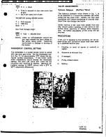
THERMOSTAT
CONTROL
SETTING
higher.
The.
thermostat
Is
a safety
device
wired
In
serles
2.
Exposure
to external
fire.
with
the
main
gas
valve.
Set
the
thermostat
con-
trol,
fig.
11,
to
approximately
100F
above
the
de-
8.
If damaged.
signed
system
temperature,
If
the
boiler
outlet
9
water
temperature
should
exceed
the
thermostat
4.
Firing
without
water.
setting,
the
main
gas
valve
will
close
but
the
circulator
will
continue
to
operate.
Maximum
ad-
5.
Scoting.
Justable
setting
Is
2400F
cut-out
with
a 50F
to
45°F
adjustable
differential.
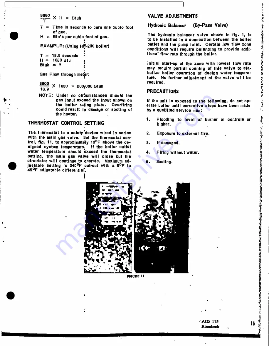
d IW.I. w -.g
FIGURE 11
•
.
.
-AOS
115
15
"
Roenbeek
FILED: NEW YORK COUNTY CLERK 02/20/2018 10:20 AM
INDEX NO. 190311/2015
NYSCEF DOC. NO. 337
RECEIVED NYSCEF: 02/20/2018


