background image

l'I

.I'.,

12$

!„"';"

I

'

"i!

Ll

I NEUTRAL

b

I

IIF

PRI

c'I

ALARM

MR

F

Through

pressure

relief

valve

opening

.

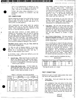
4.

Operate

the

system

for

a minimum

of

1 hour

(to

a maximum

of

24

hours).

As

noted

above,

Close

system

inlet

and

outlet

valves

at

the

system

pressure

and

temperature

must

be

g".

boiler.

such

that

the

water

does

not

boll.

Relieve

pressure

from

boiler

and

remove

p

pressure

relief

valve

from

air

purger.

5.

SYSTEM

MUST

NOW

BE

DRAINED

AND

FLUSHED.

Remove

an

amount

of

water

from

the

sys-

tem

approximately

equal

to

the

volume

of

Close

the

manual

gas

shutoff

valve

to

cleaning

solution

to

be added.

turn

off

the

burner.

This

will

allow

the

circulator

to

continue

operating

during

Add

the

cleaning

solution

to

the

system

the

flushing

procedure.

1,:I

through

the

relief

valve

opening.

Replace

relief

valve.

.

Open

the

cold

water

supply

to

the

sys-

tem.

N

.

Open

system

inlet

and

outlet

valves

at

boiler.

Connect

a

hose

to

the

boiler

drain

valve,

allow

cleaning

solution

to

flow

to

drain.

I.

3.

Pressurize

the

system.

If

necessary,

open

the

cold

water

supply

valve

and

add

pressure

All

cleaner

should

be

removed

after

15

to

to

the

system

so

that

the

water

does

not

boil

20

minutes

of

flushing.

during

the

cleaning

process.

OPERATING

INSTRUCTIONS

LIGHTING

INSTRUCTIONS

CAUTION:

Make

sure

heater

is

filled

with

water

'20v·ª°H

~

before

lighting

pilot.

The

main

(man-

ual)

gas

shutoff

valve

and

pilot

ad-

TONEXTANEL

I)

justing

valve,

}ocated

near

main

------e.

USEDI

guue

burner,

should

be

closed

for

at

least

----

SLACK

--'''å°

YELLOW

~

5

minutes.

-

REO

-ñr

~

raNexrpAnat

BALANCER

>

11F

uSED)

.

Do

not

attempt

to

light

pilot

if gas

odor

is

present.

"°"'"°

P

ALARu

Light

the

unit

in accordance

with

the

instructions

av

on

the

Lighting

and

Operating

plate

fastened

to

the

boiler.

P

SILENCE

The

pilot

is

located

under

the

boiler,

attached

7a,

to

the

right

side

of

the

main

burner.

To

reach

a

TO

1)

pilot,

remove

outer

and

inner

combustion

cham,

4

c

ber

doors.

Be

sure

toreplace

combustion

cham-

TR2

NC

I
I

ber

doors

after

lighting

unit.

nAccougLE

a

ra

SEQUENCE

OF

OPERATION

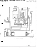
(refer

to

wiring

dia-

'

j

gram,

fig.

10).

~MRI

a

SWITCH

a3

1.

For

initial

start-up,

the

system

is

electri-

runs

e"Es"su°as

cally

energized

by

closing

the

main

dis-

u

a,s,

au

TS"'Tc"

connect

switch

after

manual

ignition

of

ΠPR2

WWGAS

I

I

pilot.

enessues

8

RA890 S

SWITCH

Panel

alarm

will

sound.

Move

alarm

sil-

MDICATOR

LAuP

ence

switch

on

control

box

to

the

OFF

s^rarvSuurosevALve

position'

OI

--rAcreaso

With

a proven

pilot

flame,

the

purge

timer

--Fiatowra'°

t

(S427B)

initiates

a

5

minute

prepurge

²

cycle.

At

the

end

of

the

prepurge

cycle,

the

TR1

contacts

open

and

TR2

contacts

aco

close.

The

alarm

silence

switch

may

now

be

moved

back

to

the

ON

position.

Alarm

F1GURE jo

should

remain

silent.

AOS

1Z9

AOS129·

13

Roenbeck

FILED: NEW YORK COUNTY CLERK 02/20/2018 10:20 AM

INDEX NO. 190311/2015

NYSCEF DOC. NO. 337

RECEIVED NYSCEF: 02/20/2018

Summary of Contents for HW-160

Page 1: ...NTIAL TYPE HYDRONIC BOILERS models HW 160 HW 200 HW 225 with FIA I ll PLAINTIFPS EXHIBIT a century Forwaitl IV LI S A PRINTEDI 3399 I PART NO 76033 374 Raenbeck FILED NEW YORK COUNTY CLERK 02 20 2018...

Page 2: ...00 HW 225 A 49 1 8 51 1 4 60 1 4 29 3 8 32 3 8 32 3 8 C 24 1 4 27 1 8 27 1 8 D 20 3 4 20 3 4 20 3 4 E 5 1 2 5 1 2 5 1 2 F 8 8 8 G 16 1 4 16 1 4 16 1 4 H 7 7 7 J 35 3 4 35 3 4 35 3 4 K 32 32 32 L 1 1 4...

Page 3: ...size piping conditions exist reduce ratings by 10 gc CIRCULATOR EXPANSION TANK SELECTIONS The following circulators are required to provide The diaphragm type expansion tank sizes listed proper water...

Page 4: ...an area where it provided will not be subject to freezing temperatures AIR REQUIREMENTS Confined Space An ample supply of air must be provided for proper combustion An insufficient supply of air will...

Page 5: ...t the replacement of another 2 Hydronic Balancer Piping in fig 1 includes appliance such as a water heater a hydronic balancer by pass between supply d and return lines This will permit adjustment It...

Page 6: ...and sys pump as Instructed on the oil tube supplied tema requiring pressure purging should be with the unit fig 8 Installed with by pass piping around the pressure reducing valve ha 4 Vent Valves It...

Page 7: ...rnetal type remove the regulator cap on underside of gas valve and turn the adjusting screw counter To trap any dirt or foreign material in the main clockwise to decrease the pressure Turn gas line a...

Page 8: ...nector plus 50 of the areas chimney with oil or coal burning equipment of the additional flue or vent connector This practice is prohibited by many local WIRING CONNECTl0NS All electrical work must be...

Page 9: ...VIEY LIMI RESET FLOW SWITCH O O 1 2 3 4 5 6 7 8 9 10 11 12 HIGH TEMP WIAE FLAME ROO P LO SAFETYSHUT OFFVALVE LOW GAS PRESSURE I SWITCH HfGH GAS THERMCCOUPLE PRESSURE SWITCH FACTORY W1RED FIGURE 4 FACT...

Page 10: ...ONEYWELL a RA832A RA832A 5 RELAY 5 RELAY THERMAL THERMAL BALANCER y See BALANCER y L o O t T T T T R adam R fame a 2 1 3 4 2 1 3 4 W W PUMP Ihiia 4 X 4 JUNCTION BOx P EiLi DELAY WITHTERMINALSTRIP 85 O...

Page 11: ...ER PANEL SE EFIG 4 FIGURE 7 ZONED SYSTEM HONEYWELL ZONE VALVES 4 4 2 4 T 24 ERMOSTAT VOLT F I 2 2 2 2 2 2 2 2 2 2 40VATRANSFORMER T 3 3 1 3 1 3 I 3 1 3 TOHANOLE UP 70 2 5ZONE VALVES ZCNE VALVES LW R T...

Page 12: ...so can produce acid concentrations of the following methods that become corrosive cause gases to form that block water circulation or lead to formation of With an acid pump or hand pump deposits on t...

Page 13: ...ION Make sure heater is filled with water TONexreANE before lighting pilot The main man J 2SED PUMP ual gas shutoff valve and pilot ad ___ay Eu OW ____ justing valve located near main an __ __ _____ b...

Page 14: ...an orange 90 seconds quality in the flame when used on L P gas This is a normal and approved char After cause of failure has been corrected acteristic the safety switch of the RA 890 relay must be ma...

Page 15: ...nces should the b gas Input exceed the input shown on If the unit la exposed to the following do not op the boiler rating plate Overfiring crate boiler until corrective steps have been made could resu...

Page 16: ...indirect heating of salt water or corrosive chemicals b when completely full of liquid free to circulate at all times c at water pressures not exceeding the pressure rating shown on the boiler d with...

Page 17: ...forwarding the replacement part from the nearest distributor and returning the claimed defective part to such distributar c All cast necessary ar incidental far any materials and or permits required...

Page 18: ...8 51 1 4 60 1 4 B 29 3 8 32 3 8 32 3 8 C 24 1 4 27 1 8 27 1 8 D 20 3 4 20 3 4 20 3 4 E 5 1 2 5 1 2 5 1 2 F 8 8 8 G 18 1 4 16 1 4 16 1 4 H 7 7 7 J 35 3 4 35 3 4 35 3 4 K 32 32 32 L 1 1 4 1 1 4 1 1 4 M...

Page 19: ...unusual pick up or large size piping conditions exist reduce ratings by 10 CIRCULATOR EXPANSION TANK SELECTIONS The following circulators are required to provide The diaphragm type expansion tank siz...

Page 20: ...l be An ample supply of air must be provided for proper Provided combustion An insufficient supply of air will result in a yellow luminous burner flame causing Confmed Space carboning or sooting of th...

Page 21: ...or to permit the rdplacement of another 2 Hydronic Balancer Piping in fig 1 includes appliance such as a water heater a hydronic balancer by pass between supply and return lines This will permit adju...

Page 22: ...r la oiled and op tems requiring predsure purging abould be crated by the manufacturer IT MUST BE Installed with by ass piping around the OILED AGAIN BEFORE OPEFIATED Oil pressure reducing valve the t...

Page 23: ...s lines shall be remove the regulator cap on underside of gas of the metabto metal type valve and turn the adjusting screw counter To trap any dirt or foreign material In the main clockwise to decreas...

Page 24: ...with oil or coal burning equipment of the additional flue or vent connector This practice is prohibited by many local Periodically examine the venting system for obstructions and or deteriation of ven...

Page 25: ...TEMP a l RHEE a REARVJEY ANUAL is m RESET FLOW SW1TCH 8 o a o I II 2 5 7 1 11 12 FLAME HIGH TEMP WIAE ROD SAFETYSHUT PlLOT OFFVA WE Rl R LOW GAS PRESSURE SWITCH HIGH GAS THERMOC OUPLE PRESSURE SWITCH...

Page 26: ...HONEYWELL RA 832A Q RA832A 5 RELAY 5 BEyAY THERMAL THERMAL 8ALANCER y O Q BALANCER g y Q Q 0 R 0 R e 2 1 3 4 O 2 1 3 4 iPUMP ILiii 4 X 4 JUNCTION BOX O AP Ilaiii OELAyl WITHTERMINALSTRIP aa aa SMITHNO...

Page 27: ...LER PAMEL SEE MG FIGURE 7 ZONED SYSTEM HONEYWELL ZONE VALVES 2 4 2 4 2 4 2 4 THERMOSTAT Z4 VOLT Ii il 2 1 2 2 2 2 2 2 Z 4 4 4 fl 40VATRANSFORM ER 1 3 3 3 T 3 1 3 1 3 TOHANDLE UF TO q a 6ZONE VALVES ZO...

Page 28: ...re to do so can produce acid concentrations of the following methods that become corrosive cause gases to form that block water circulation or lead to formation of With an acid pump or hand pump depos...

Page 29: ...lighting pilot The main man ual gas shutoff valve and pilot ad TONEXTANEL I justing valve ocated near main e USEDI guue burner should be closed for at least SLACK YELLOW 5 minutes REO r raNexrpAnat BA...

Page 30: ...an orange 90 seconds quality In the flame when used on L P gas This is a normal and approved char After cause of failure has been corrected acteristic the safety switch of the RA 890 relay must be man...

Page 31: ...shown on If the unit is exposed to the following do not op the boiler rating plate Overfiring crate boiler until corrective steps have been made could result in damage or sooting of by a qualified se...

Reviews: