of
gas.
f
'
'A.
';.
'4
«",r'-
s+)~
«„i'Jl,
'-.
','
*
„;
«r
r
t
3600
X
H
=
Btuh
VALVE
ADJUSTMENTS
T
T
=
Time
is
seconds
to
burn
one
cubic
foot
Hydronic
Balancer
(By-Pass
Valve)
e
H
=
Btu
s
er cubic
foot
of gas.
The
hydronic
balancer
valve
shown
in
fig.
1,
is
to
be
installed
in
a connection
between
the
boiler
EXAMPLE:
(Using
HW-200
boiler)
outlet
and
the
pump
inlet.
Certain
low
flow
zone
conditions
will
require
balancing
to
provide
addi-
T
=
19
seconds
tional
flow
rate
through
the
boiler.
H
=
1050
Btu
Btuh
=
?
Initial
start-up
of
the
zone
with
lowest
flow
rate
may
require
partial
opening
of
this
valve
to
sta-
Gas
Flow
through
meter:
balize
boiler
operation
of
design
water
tempera-
ture.
No
further
adjustment
of
the
valve
will
be
3600
required.
X
1050
=
199,000
Btuh
l9
PRECAUTIONS
NOTE:
Under
no
circumstances
should
the
gas
input
exceed
the
Input
shown
on
If
the
unit
is
exposed
to
the
following,
do
not
op-
the
boiler
rating
plate.
Overfiring
crate
boiler
until
corrective
steps
have
been
made
could
result
in
damage
or
sooting
of
by
a qualified
service
man:
the
heater.
1.
Flooding
to
level
of
burner
or
controls
or
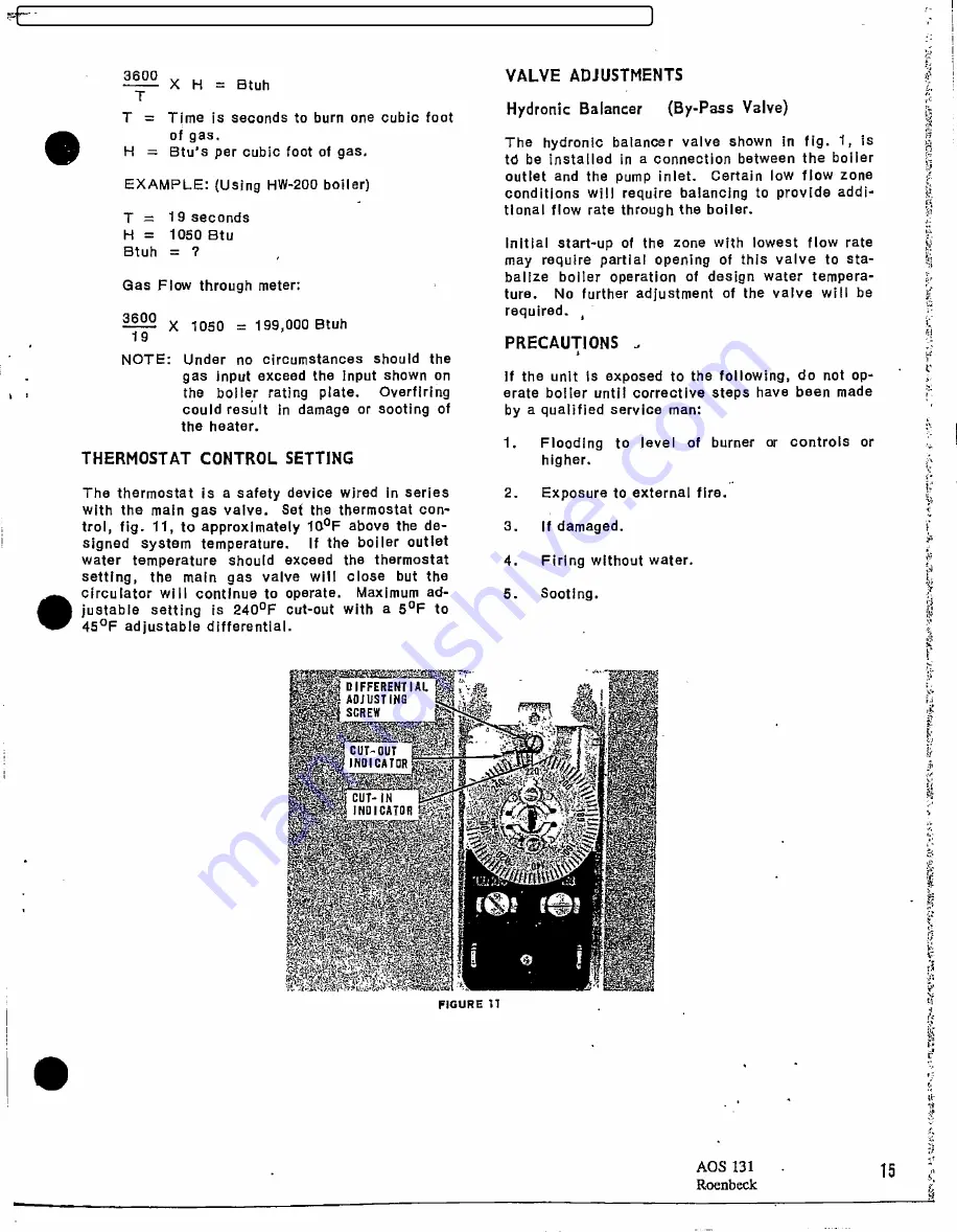
THERMOSTAT
CONTROL
SETTING
higher.
The
thermostat
is
a safety
device
wired
in
series
2.
Exposure
to external
fire.
with
the
main
gas
valve.
Set
the
thermostat
con-
.
trol,
fig.
11,
to
approximately
100F
above
the
de-
3.
If damaged.
signed
system
temperature.
If
the
boiler
outlet
water
temperature
should
exceed
the
thermostat
4.
Firing
without
water.
setting,
the
main
gas
valve
will
close
but
the
circulator
will
continue
to
operate.
Maximum
ad-
5.
Scoting.
justable
setting
is
240°F
cut-out
with
a 5°F
to
45°F
adjustable
differential.
«+>~ DIFFERIENTIAL ~up~.,'..~
~'
ADJUSTING
SCREW
CUT-0UT
INDICATOR
CUT-IN
INDICATOR
F]GURE D
AOS
131
.
15
Lg
FILED: NEW YORK COUNTY CLERK 02/20/2018 10:20 AM
INDEX NO. 190311/2015
NYSCEF DOC. NO. 337
RECEIVED NYSCEF: 02/20/2018


