Piping"
~
FOREWORD
This
design
compiles
with
ANS
Z21.10.3
as
a low
in
the
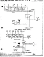
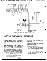
diagrams
as
these
are
necessary
for
check-
pressure
boiler.
ing
the
operation
of
the
boiler.
4
.
MAKE
SURE
the
gas
on
which
the
boiler
will
Detailed
installation
diagrams
are
in
this
manual.
operate
is
the
same
as that
specified
on
the
boiler
These
diagrams
will
serve'to
provide
the
installer
Model
and
Rating
Plate.
with
a reference
for
the
materials
and
method
of
piping
suggested
.
It
is
highly
essential
that
all
NOTE:
It
is
recommended
that
the
instructions
water
and
gas
piping,
and
the
electrical
wiring,
as
outlined
in
the
latest
publication
of
be
installed
and
connected
as
shown
in
the
ANS
booklet
Z21.30
"Installation
of Gas
diagrams.
Appliances
and
Gas
P i
ping"
also
be
fol-
lowed.
This
Manual
can
be
purchased
Check
the
diagrams
thoroughly
before
starting
from
the
American
Gas
Association
Lab-
installation
to
avoid
possible
errors
and
to
mini-
'oratories,
8501
E.
Pleasant
Valley
Rd.,
mize
time
and
materials
cost.
Cleveland,
Ohio
44131.
Particular
attention
should
be
given
to
the
instal-
Unless
otherwise
stated,
these
instructions
shall
lation
of
thermometers
at
the
locations
indicated
apply
to
all
residential
type
boilers.
I
INSTALLATION
INSTRUCTIONS
LOCATION
When
'installing
the
boiler,
consideration
must
If the
unconfined
space
is
within
a building
of
un-
be
given
to
proper
location.
Location
selected
usually
tight
construction,
air
for
combustion,
should
be
as
close
to
the
stack
or
chimney
as
ventilation
and
draft
hood
dilution
shall
be
ob-
practicable,
and
as
centralized
with
the
piping
tained
from
outdoors
or
from
spaces
freely
com-
system
as
possible.
municating
with
the
outdoors.
Permanent
open-
ing(s)
having
a total
free
area
of
not
less
than
one
The
boiler
should
also
be
located
near
a floor
square
inch
per
5,000
Btuh
total
input
shall
be
drain
to
dispose
of
water
and
in
an
area
where
it
provided.
will
not
be subject
to freezing
temperatures.
AIR
REQUIREMENTS
Confined
Space
An
ample
supply
of air
must
be provided
for
proper
combustion.
An
insufficient
supply
of
air
will
ALL
AIR
FROM
INSIDE
BUILDING
result
in
a yellow,
luminous
burner
flame,
causing
carboning
or
sooting
of
the
finned
heat
exchanger
The
confined
space
shall
be
provided
with
two
and
burner,
and
possible
damage
to
the
boiler,
permanent
openings,
one
near
the
top
of
the
en-
closure
and
one
near
the
bottom.
Each
opening
Chemical
Vapors
I
shall
have
a free
area
of
not
less
than
one
square
inch
per
1,000·Btuh
of
the
total
input
rating
of
all
When
destructive
or
corrosive
chemical
vapors
appliances
in
the
enclosure,
freely
communicating
(such
as
dry
cleaning
fluids,
pressure
can
propel-
with
interior
areas
having
in
turn
adequate
infil-
lents,
refrigerants,
chlorine,
bleaching
compounds,
tration
from
the
outside.
flammables,
etc.)
may
be
present,
even
in
minute
quantities
in the
combustion
air
supply
provisions
ALL
AIR
FROM
OUTDOORS
should
be
made
to
take
all
air
(100%)
for
combus-
tion
and
draft
hood
dilution
from
outside
of
build-
The
confined
space
shall
be
provided
with
two
ing
and
at
a
point
remote
from
the
discharge
of
permanent
openings,
one
in
or
near
the
top
of
the
dry
cleaning
equipment
and/or
building
exhaust
enclosure
and
one
in
or
near
the
botto'm.
When
systems,
directly
cornmunicating
with
outdoors
or
by
means
of
vertical
ducts,
each
opening
shall
have
a free
Unconfined
Space
area
of
not
less
than
one
square
inch
per
4,000
Btuh
of
total
Input
rating
of
al.I
appliances
in
the
In
buildings
of
conventional
frame,
brick
or
stone
enclosure.
If
horizontal
ducts
are
used
each
construction,
unconfined
spaces
normally
provide
opening
shall
have
a
free
area
of
not
less
than
adequate
air
for
combustion,
ventilation
and
draft
one
square
inch
per
2,000
Btub
of
total
input
of
hood
dilution.
all
appliances
in
the
enclosure.
4
AOS
104
Roeabeek
FILED: NEW YORK COUNTY CLERK 02/20/2018 10:20 AM
INDEX NO. 190311/2015
NYSCEF DOC. NO. 337
RECEIVED NYSCEF: 02/20/2018


