I
I,
GAS
CIRCULATOR
h
C
/
J
S"
Where
an
exhaust
fan
Is
Installed
in
the
same
LEVELLING
.
room
with
a
boiler,
suffialent
openings
for
air
must
be
provided
in
the
walls.
Undersized
open-
The
boiler
should
be
checked
during
and
after
ings
will
cause
air
to
be
drawn
into
the
room
installation
to
be certain
that
it
is
level.
through
the
chimney,
causing
poor
combustion.
Sooting
may
result
in
serious
damage
to
the
If
the
unit
is
not
level,
shims
should
be
inserted
boiler.
under
the
unit
to
correct
this
condition.
INSTALLATION
CLEARANCES
WATER
LINE
CONNECTIONS
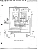
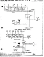
(Fig.
1)
These
units
are
listed
for'
for
installation
with
the
following
minimum
clearances:
In
all
cases,
local
codes
have
authority
over
the
following
instructions:
6"
between
sides
and
rear
of
unit
and
combustion
construction.
1.
Supply
and
Return
Lines.
Be
sure
that
sys-
tem
supply
and
return
lines
are
connected
to
24"
should
be
provided
at the
front
of
the
unit
for
the
proper
boiler
connections,
fig.
1,
to
pro-
proper
servicing.
In
a
utility
room
installation,
vide
up flow
of water
through
the
boiler.
the
door
shall
be
wide
enough
to allow
the
boiler
to
enter
or
to
permit
the
replacement
of
another
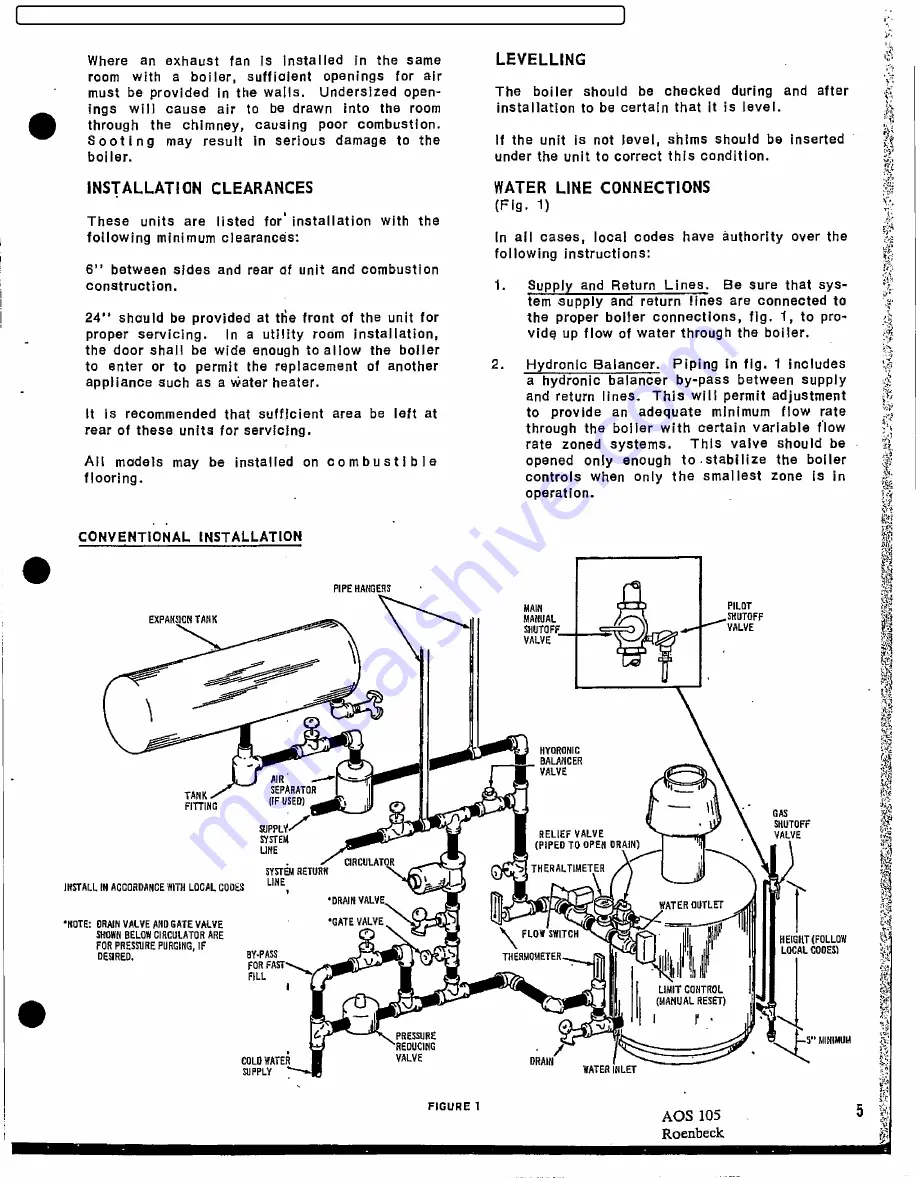
2.
Hydronic
Balancer.
Piping
in
fig.
1 includes
appliance
such
as
a water
heater,
a
hydronic
balancer
by-pass
between
supply
d
and
return
lines.
This
will
permit
adjustment
It
is
recommended
that
sufficient
area
be
left
at
to
provide
an
adequate
minimum
flow
rate
rear
of
these
units
for
servicing.
through
the
boiler
with
certain
variable
flow
rate
zoned
systems.
This
valve
should
be
S
All
models
may
be
installed
on
combustible
opened
only
enough
to.stabilize
the
boiler
flooring.
controls
when
only
the
smallest
zone
is
in
operation.
CONVENTIONAL
INSTALLATl0N
t
PIPEHANGERS
MAIN
PILOT
EXPANSICNTANK
MANUAL
SHVTOFF
SHOTOFF_,_
VALVE
VALVE
HYORONIC
BALANCER
AIR
--
VALVE
TANK
SEPARATOR
FITTING
[FFUSED)
,
SUPPLy
I
SKUTOFF
sygy
RELLEFVALVE
VALVE
LINE
(PIPEDTOOPENDRAIN)
SYSTEM
RETURN
)
THERALTIMETER
NSTALL
INACCORDANCE
WITHLOCALCODES
UNE
*DRAIM
VALVE
WER COTLEr
*NOTE:ORAIN
VALVEANDGATE
VALVE
*GATEVALVE
)if
SHOWN
BELOW
CIRCULATOR
ARE
FLOWSWITCH
ii
FORPRESSllRE
PURGING,
IF
!'
HEIGitT
(FOLLOW
DESIRED,
BY-PASS
.3
THERM0METER
LOCAL
CODES)
FORFAST
FILL
I
LIMITCONTROL
t
(MANUAL
RESET)
E
PRESSURE
-5" AllNIMUM
REDilClNG
.
COLD
WATEÑ
VALVE
DRAIN
SUPPLY
WATER
lNLET
FIGuRE 1
5
AOS
105
Roenbeck
P~
FILED: NEW YORK COUNTY CLERK 02/20/2018 10:20 AM
INDEX NO. 190311/2015
NYSCEF DOC. NO. 337
RECEIVED NYSCEF: 02/20/2018


