Instruction manual SGS
17
gis
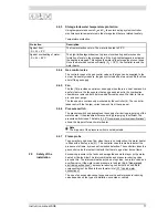
2.4.3
Storage tank water temperature protection
Using temperature sensors S
2
and S
3
, the solar heating system controller
monitors several temperatures in the storage tank that are related to safety.
Temperature protection
2.4.4
Gas control valve
The controller opens the gas control valve so that gas can be supplied to the
burner. As a safety measure, the gas control valve has two valves. Both valves
shut off the gas supply.
2.4.5
Fan
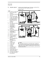
The fan (18) provides an optimum air supply when there is a heat demand. As
a safety feature, the fan ensures that any gases present in the combustion
chamber are removed, both before and after combustion. We refer to this as
pre- and post-purge.
The fan speed is continuously monitored by the controller (4). The controller
takes control if the fan rpm varies too much from the value set.
2.4.6
Pressure switch
The pressure switch only guarantees the supply of air during pre-purging of the
water heater. If the pressure difference during pre-purging is sufficient, the
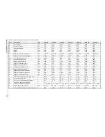
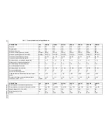
pressure switch closes. The table (3.4.2 "General and electrical specifications")
shows the trip point for each water heater.
Note
The trip point of the pressure switch is not adjustable.
2.4.7
Flame probe
To ensure that no gas can flow when there is no combustion, the water heater
is fitted with a flame probe (21). The controller uses this probe to detect the
presence of a flame, by means of ionisation detection. The controller closes the
gas control valve the instant it detects that there is a gas flow but no flame.
2.5
Safety of the
installation
Excessive pressure in the tank can damage the enamelled layer (in the water
heater) or the tank itself. An inlet combination and pressure-reducing valve
prevents this. The inlet combination acts as a stop valve, non-return valve and
overflow valve. If the water mains pressure is too high (3.4.2 "General and
electrical specifications"), a pressure-reducing valve must be used. Both
components must be fitted in the cold water inlet (3.7 "Vented water
connections").
The use of an expansion vessel, expansion valve and/or pressure reducing
valve depends on the type of installation: unvented or vented.
Protection
Description
Against frost:
- S
2
, S
3
< 5°C
The frost protection cuts in. The water is heated to 20°C.
Against overheating of water:
- S
2
, S
3
> 85°C
The high-limit safeguard serves to prevent overheating and/or excessive
formation of scale in the storage tank. If the high-limit safeguard is activated,
the heating is stopped. This causes the water in the storage tank to cool down.
Once the water has cooled sufficiently (S
3
< 78°C), the controller resets the
water heater.
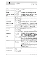
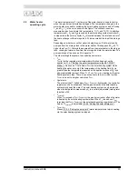
Summary of Contents for SGS - 100
Page 7: ...4 Instruction manual SGS gis...
Page 11: ...Contents 8 Instruction manual SGS...
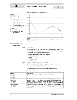
Page 23: ...Working principle of the water heater 20 Instruction manual SGS 2 gis...
Page 37: ...Installation types 34 Instruction manual SGS Installation 3...
Page 57: ...Conversion to a different gas category 54 Instruction manual SGS 4 is...
Page 65: ...Draining 62 Instruction manual SGS 6 gis...
Page 71: ...Status of the water heater 68 Instruction manual SGS 8 gis...
Page 75: ...Shutting down 72 Instruction manual SGS 10 gis...
Page 103: ...Service interval 100 Instruction manual SGS 14 is...
Page 112: ...Instruction manual SGS 109 is...
Page 119: ...Instruction manual SGS 116...


