Instruction manual SGS
41
is
3.11.4
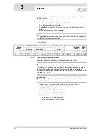
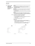
Isolating transformer
An isolating transformer should be used if there is a case of 'floating neutral'.
Note
The total power consumed by the appliance goes via the isolating
transformer.
1. Refer to the fitting instructions provided with the isolating transformer.
(Contact the supplier for details of the correct isolating transformer.)
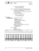
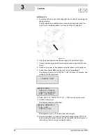
2. Connect the neutral (N), live (L) and earth ( ) of the power cables to
terminals 4 through 9 of the connection block according to the
table (3.11.2 "Preparation").
3. Fit the cables in the strain relief.
4. If you have no more connections to make:
-
Fit the cover on the terminal block.
-
Fit the covers onto the water heater.
5. Connect the power cable to the isolator.
3.11.5
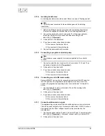
Connecting a program-controlled pump
Note
The maximum power capacity for a pump regulated by the controller
is 100W.
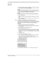
1. Connect neutral (N), live (L) and earth ( ) to terminals 13, 14 and 15 as
indicated in the table (3.11.2 "Preparation").
2. Fit the cable in the strain relief.
3. If you have no more connections to make:
-
Fit the cover on the terminal block.
-
Fit the covers onto the water heater.
3.11.6
Connecting an extra ON mode switch
External ON/OFF is an option for connecting an external ON/OFF switch. In
the OFF position, the programmed operating mode is active. In the ON
position, the programmed operating mode is overruled, and "ON mode" is
active.
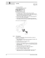
1. Connect leads (X
3
and X
4
) to terminals 21 and 22 according to the
table (3.11.2 "Preparation").
2. Fit the cable in the strain relief.
3. If you have no more connections to make:
-
Fit the cover on the terminal block.
-
Fit the covers onto the water heater.
3.11.7
Connect additional error signal
The appliance has a
relay
terminal that is switched when an error is detected.
This
can be used to signal errors, for example with a bulb. A 230V circuit can
be
powered directly. Other voltages require a relay prescribed by the
manufacturer.
1. Connect the phase cables (X
1
and X
2
) to points 10 and 11 according to the
table (3.11.2 "Preparation"). If required, connect earth ( ) to terminal 12.
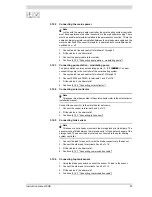
2. Fit the cable in the strain relief.
Summary of Contents for SGS - 100
Page 7: ...4 Instruction manual SGS gis...
Page 11: ...Contents 8 Instruction manual SGS...
Page 23: ...Working principle of the water heater 20 Instruction manual SGS 2 gis...
Page 37: ...Installation types 34 Instruction manual SGS Installation 3...
Page 57: ...Conversion to a different gas category 54 Instruction manual SGS 4 is...
Page 65: ...Draining 62 Instruction manual SGS 6 gis...
Page 71: ...Status of the water heater 68 Instruction manual SGS 8 gis...
Page 75: ...Shutting down 72 Instruction manual SGS 10 gis...
Page 103: ...Service interval 100 Instruction manual SGS 14 is...
Page 112: ...Instruction manual SGS 109 is...
Page 119: ...Instruction manual SGS 116...


