background image

Starting the water heater

70

Instruction manual SGS

9

gis

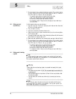
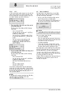
When the water heater starts, it will run through the 
following steps:
1. The water temperature drops below the set 

temperature of (for example) 

65

°C. The controller 

detects a heat demand and starts the operating 
cycle.
-

The icon   is activated.

-

The message 

HEAT DEMAND

 appears.

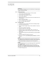
2. Once demand is registered, the fan is started to 

vent any gases that may be present. This phase is 
called pre-purge and lasts about 15 seconds.
-

The icon   is activated.

-

The message 

PRE PURGE

 appears.

3. During the pre-purge, the pressure switch closes.

-

The icon   is activated.

-

The message 

PRESSURE SWITCH


appears.

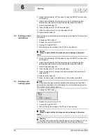
4. This is then followed by the (pre-)glow of the hot 

surface igniter.
-

The icons   and   are dimmed

-

The icon   is activated.

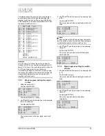
5. After a number of seconds pre-glow, the gas 

control valve is opened and ignition takes place.
-

The icon   is activated.

-

The message 

IGNITION

 appears.

6. After ignition, the flame is detected and the 

appliance will be running. This means that actual 
heating has started:
-

The icon   is dimmed.

-

The icon   is activated.

-

The message 

RUNNING

 appears.

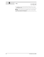
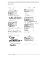
7. When the water is up to temperature, the heat 

demand ceases and the post-purge starts. This 
takes about 25 seconds.
-

The icons  ,   and   are dimmed.

-

The icon   is activated.

-

The message 

POST PURGE

 appears.

8. Following the post-purge, the fan stops and the 

pressure switch opens:
-

The icons   and   are dimmed.

-

The message 

POST PURGE

 vanishes.

With any subsequent heat demand, the heating cycle 
will resume from step 1.

ON

Ê

13:45 Thursday

63ÉC

Tset 65ÉC

HEAT DEMAND

ON

Ê Ê

13:45 Thursday

63ÉC

Tset 65ÉC

PRE PURGE

ON

Ê Ê Ê

13:45 Thursday

63ÉC

Tset 65ÉC

PRESSURE SWITCH

ON

Ê

Ê

13:45 Thursday

63ÉC

Tset 65ÉC

GLOW PLUG

a

a

a

a

ON

Ê

Ê Ê

13:45 Thursday

63ÉC

Tset 65ÉC

IGNITION

ON

Ê

 Ê 

Ê

13:45 Thursday

63ÉC

Tset 65ÉC

RUNNING

ON

Ê Ê 

13:45:00 

Thursday

65ÉC

Tset 65ÉC

POST PURGE

ON

14:05 Thursday

65ÉC

a

a

a

a

Summary of Contents for SGS - 100

Page 1: ...0311183 Innovation has a name Installation User and Service Manual Condensing High Efficiency Gas Solar Water Heater SGS 28 30 50 60 80 100 120 SGS 3015 Changes Reserved...

Page 2: ...your installer A O Smith UK Unit B8 Amstrong Mall Southwood Business Park Farnborough Hampshire GU14 0NR www aosmith co uk A O Smith Water Heaters is a trading name of Advance Services Sales Ltd Reg...

Page 3: ...nalize the maintenance carry out the following steps 1 Fill the water heater 5 Filling 2 Start the water heater 9 Starting the water heater 3 Check the CO2 value 3 12 3 CO2 adjustment 4 Check the swit...

Page 4: ...E2 17 3 Electrical diagram Electrical diagram solar heating system 0309687b R2 0 1 brown 2 blue 3 yellow green 4 black 5 white 6 grey beige 7 green 8 yellow...

Page 5: ...or S1 solar collector DD Temperature sensor S2 tank EE Combined Q T sensor incl temperature sensor S4 solar collector return FF Communication between the water heater controller and the solar Heating...

Page 6: ...hat stated in this manual and use other than in accordance with the General Conditions registered at the Chamber of Commerce Refer further to the General Conditions These are available on request free...

Page 7: ...4 Instruction manual SGS gis...

Page 8: ...3 2 Packaging 21 3 3 Ambient conditions 21 3 4 Technical specifications 23 3 5 Installation diagram 29 3 6 Unvented water connections 30 3 7 Vented water connections 30 3 8 Gas connection 31 3 9 Sola...

Page 9: ...the mains 71 10 4 Decommissioning the water heater for a long period 71 11 Main menu 73 11 1 Introduction 73 11 2 Notation convention for menu related instructions 73 11 3 Switching to ON mode 73 11 4...

Page 10: ...ter side maintenance 102 15 4 Gas side maintenance 103 15 5 Solar collector maintenance 104 15 6 Finalizing maintenance 104 16 Warranty certificate 105 16 1 General warranty 105 16 2 Tank warranty 105...

Page 11: ...Contents 8 Instruction manual SGS...

Page 12: ...heaters and and are entitled to bear the CE mark Warning Read this manual carefully before starting the water heater for the first time Failure to read the manual and to follow the printed instructio...

Page 13: ...r human consumption Part 2 Design BS 5546 Specification for installation of hot water supplies for domestic purposes using gas fired appliances of rated input not exceeding 70 kW BS 5440 Flueing and v...

Page 14: ...and the set water temperature Note To determine the correct service interval it is recommended to arrange for the service and maintenance engineer to check the water heater on both the water and gas s...

Page 15: ...menu This chapter describes the main menu of the display This is the actual menu for the user However the installation engineer and service and maintenance engineers will also need to use this menu S...

Page 16: ...air required for combustion is delivered by the fan 18 The gas is supplied via the gas control valve 16 and the venturi 30 on the intake side of the fan The 1 1 gas to air ratio always guarantees the...

Page 17: ...control panel 7 temperature sensor T1 8 combustion chamber 9 anode 10 tank 11 heat exchanger 12 inspection and cleaning opening 13 temperature sensor T2 14 cold water inlet 15 drain valve 16 gas cont...

Page 18: ...Tset Tset is the the required water temperature that has been set on the appliance 11 4 1 Setting the water temperature via the SET POINT MENU As soon as T1 falls below Tset the solar heating system s...

Page 19: ...ure sensors Temperature protection Legend A Gas burner on B Gas burner off T1 No heat demand so water is not heated Water heated via solar heating system Water heated via solar heating system and gas...

Page 20: ...4 7 Flame probe To ensure that no gas can flow when there is no combustion the water heater is fitted with a flame probe 21 The controller uses this probe to detect the presence of a flame by means o...

Page 21: ...k becomes too high or the water temperature becomes too hot the valve will open The hot water can now flow out of the tank Because the water heater and storage tank are under water supply pressure col...

Page 22: ...ssel as well as the expansion vessel 2 7 2 Expansion valve The solar heating system is equipped with an expansion valve The expansion valve monitors the pressure in the solar heating system Should the...

Page 23: ...Working principle of the water heater 20 Instruction manual SGS 2 gis...

Page 24: ...n to a different gas category 3 2 Packaging To avoid damaging the water heater remove the packaging carefully We recommend unpacking the water heater at or near its intended location Caution The water...

Page 25: ...e type of storage tank 3 3 3 Water composition The appliance is intended for heating drinking water The drinking water must comply with the regulations governing drinking water for human consumption T...

Page 26: ...ess to the storage tank it is recommended that the following clearances are observed All sides of the storage tank 50 cm Above the storage tank space for anode replacement 100 cm Note When installing...

Page 27: ...24 Instruction manual SGS 3 4 1 Dimensions of the water heater Top and front view of the appliance Legend See the table SGS 28 30 50 60 SGS 80 100 120...

Page 28: ...y mm 265 255 255 255 225 225 225 N Height of hot water outlet mm 1485 2015 2015 2015 2060 2060 2060 Ny y position of hot water outlet mm 205 205 205 205 205 205 205 P Height of cleaning opening mm 265...

Page 29: ...4 4 5 5 5 Adjustment range for solar differential o C 0 8 0 8 0 8 0 8 0 8 0 8 0 8 Solar differential default value o C 7 2 2 2 5 5 5 Adjustment range for solar limit o C 65 80 65 80 65 80 65 80 65 80...

Page 30: ...s pressure of cold water supply vented kPa bar 800 8 Maximum mains pressure of cold water supply unvented kPa bar 550 5 5 Maximum mains pressure of the protected cold supply setup kPa bar 500 5 T P ov...

Page 31: ...0 9 0 1 0 8 9 1 0 8 9 1 0 8 9 1 0 Gas consumption m3 h 3 1 3 2 5 0 6 0 8 3 10 1 12 3 Gas category 3P G31 37 50 mbar Diameter of the venturi restrictor mm 6 00 6 00 6 00 6 00 6 60 6 60 6 60 Nominal lo...

Page 32: ...ry 37 combined Q T sensor optional 38 solar heating system pump station modulating mandatory 42 Solar heating system controller A cold water supply B hot water supply C circulation pipe D gas supply E...

Page 33: ...re of the tap water 2 Fit the T P valve 3 3 Fit a stop valve 11 in the hot water outlet pipe for servicing 3 6 3 Circulation pipe See C in the installation diagram 3 5 Installation diagram If an immed...

Page 34: ...oints a circulation pump can be installed This improves comfort and reduces water wastage 1 Fit a circulation pump 6 of the correct capacity for the length and resistance of the circulation system 2 F...

Page 35: ...s table 3 11 2 Preparation 4 Connect the communication cable between the solar heating system controller and the water heater see electrical diagram 17 4 Electrical diagram solar heating system and co...

Page 36: ...discusses installation types C13 and C33 in detail If the water heater has to function in accordance with B23 C43 C53 or C63 you can obtain more information by contacting A O Smith The figure and tab...

Page 37: ...Installation types 34 Instruction manual SGS Installation 3...

Page 38: ...you use less than the stated maximum pipe length the maximum number of bends still may not be exceeded The following example illustrates how to use the table Installation type Description B23 Air for...

Page 39: ...vely of a type approved for the water heater Use of an incorrect roof or wall mounted flue terminal can cause the installation to malfunction Concentric wall flue terminal specifications C13 IMD 0791...

Page 40: ...61 1 Manufacturer Muelink Grol Type Skyline 3000 28 60 and Mugro 2000 80 120 Pipe material Construction Concentric Flue gas discharge Thick walled aluminium with lipped sealing ring Air supply Thin wa...

Page 41: ...ition piece can be ignored According to the table 4 6 metres must be added for each bend This brings the total pipe length to 4 6 x 8 10 36 8 10 46 8 m This is less than the maximum length of 55 metre...

Page 42: ...sential to connect the mains live L to the live of the water heater and the mains neutral N to the neutral of the water heater Caution There must be no potential difference between neutral N and earth...

Page 43: ...he mains power by means of a permanent electrical connection A double pole isolator with a contact gap of at least 3 mm must be fitted between this permanent connection and the water heater The power...

Page 44: ...3 11 2 Preparation 2 Fit the cable in the strain relief 3 If you have no more connections to make Fit the cover on the terminal block Fit the covers onto the water heater 3 11 6 Connecting an extra O...

Page 45: ...overs onto the water heater 3 12 Electrical connection of the solar heating system This section covers the following topics Preparation Connecting the mains power Connecting pump station modulating pu...

Page 46: ...nd 2 of J18 3 Fit the cables in the strain relief 4 Continue 3 12 4 Connecting solar collector 3 12 4 Connecting solar collector Note This sensor must be mounted in the solar collector refer to the so...

Page 47: ...ections Fit the cover over the controller 3 12 8 Connecting extra head pump Note This pump is essential if a greater head is required When the system has such a high resistance 66 kPa that the pump in...

Page 48: ...checking the supply pressure gas control valve pressure CO2 value and switching pressure 3 13 1 Procedure for checking the supply pressure To check the supply pressure proceed as follows 1 Isolate 10...

Page 49: ...g the isolator on the appliance 9 Switch the controller ON by setting the 0 I switch to position I The display will now show INTERNAL CHECK for about 10 seconds and will then go to the main menu 10 Se...

Page 50: ...e If the appliance does not have a reducing valve continue from adjusting the CO2 value 3 13 3 CO2 adjustment To check the gas control valve pressure proceed as follows 1 Isolate 10 3 Isolating the wa...

Page 51: ...3 3 CO2 adjustment To check the CO2 value under full load and partial load and to adjust it if necessary proceed as follows 1 Isolate 10 3 Isolating the water heater from the mains the appliance from...

Page 52: ...value stated in the table 3 4 3 Gas data SGS 28 to 60 13 If necessary adjust the CO2 value using the adjuster screw until the value is within the range listed in the table of CO2 values Use the Allen...

Page 53: ...19 From the service menu select SERVICE OPERATION PARTIAL LOAD Confirm with The appliance is now in PARTIAL LOAD mode and will ignite 20 The appliance is now running at PARTIAL LOAD Read the value fr...

Page 54: ...13 4 Switching pressure measurement To measure the switching pressure proceed as follows 1 Isolate 10 3 Isolating the water heater from the mains the appliance from the power supply 2 Carefully remov...

Page 55: ...w 11 Check whether the measured value matches the value from the table 3 4 3 Gas data Note If the message PRESSURE SWITCH does not appear there is a fault This must be resolved first by a qualified se...

Page 56: ...ial conversion kit You can order the conversion kit you need from the supplier of your appliance The conversion kit contains all the parts needed to do the conversion A description of how to do the co...

Page 57: ...Conversion to a different gas category 54 Instruction manual SGS 4 is...

Page 58: ...ted Unused numbers are not applicable 1 pressure relief valve mandatory if the mains water pressure is too high 3 T P valve 4 stop valve recommended 5 non return valve mandatory 6 circulation pump opt...

Page 59: ...off points 7 The water heater is now under water supply pressure There should now be no water coming out of the inlet combination expansion valve or if used out of the T P valve 3 If there is the caus...

Page 60: ...combination 5 Plug the glycol pump into a mains socket 6 Start the glycol pump using the ON OFF switch on the glycol pump 7 Stop the glycol pump as soon as the pressure gauge on the pump station begin...

Page 61: ...SGS 5 gis 13 Close the valve of the inlet combination and disconnect the glycol pump including the hoses Note Dispose of the residual glycol in the filler hose in an environment friendly manner and a...

Page 62: ...valve 4 stop valve recommended 5 non return valve mandatory 6 circulation pump optional 9 drain valve 10 manual gas valve mandatory 11 service stop valve 12 temperature gauge optional 13 condensation...

Page 63: ...e control panel 6 Isolate the water heater from the power supply by setting the isolator between the water heater and the mains power supply to position 0 7 Shut off the gas supply 10 8 Close the stop...

Page 64: ...rain point 9 Open the air bleed point 26 of the solar heating system 10 Close the drain point when the jerry can is full 11 Insert the hose in a new jerry can 12 Repeat steps 6 and 7 until no further...

Page 65: ...Draining 62 Instruction manual SGS 6 gis...

Page 66: ...ON OFF switch on controller The ON OFF switch of the controller turns the water heater ON and OFF Note that in the OFF position the water heater remains electrically live in order for the continuous...

Page 67: ...own further to see the options EXTRA PERIOD and SETTINGS The selected option is confirmed using Pressing the button takes you back one page in a menu and discards all options selected in the current m...

Page 68: ...ne the text ON line two the time the day and T1 9 3 The appliance s heating cycle line three the programmed water temperature Tset line four is empty when the water heater is idle or depending on the...

Page 69: ...Note Setting and if necessary programming of the basic operating modes are described in the main menu 11 Main menu chapter 8 3 Error conditions The figure shows an example of an error condition If th...

Page 70: ...s when the anode protection is no longer active If the message appears you must contact your service and maintenance engineer Note The water heater continues to function when this message appears 8 6...

Page 71: ...Status of the water heater 68 Instruction manual SGS 8 gis...

Page 72: ...ppliance is now in ON mode If there is a heat demand the appliance will run through the heating cycle 9 3 The appliance s heating cycle If the heating cycle is not run there is no heat demand if this...

Page 73: ...ed and ignition takes place The icon is activated The message IGNITION appears 6 After ignition the flame is detected and the appliance will be running This means that actual heating has started The i...

Page 74: ...ng the water heater from the mains The water heater may only be isolated from mains power in the correct way The correct procedure is as follows 1 Activate the MENU with 2 Position the cursor in front...

Page 75: ...Shutting down 72 Instruction manual SGS 10 gis...

Page 76: ...u fail to make any selection with the main menu open then after 30 seconds the water heater will automatically return to the mode it was previously in 11 2 Notation convention for menu related instruc...

Page 77: ...The appliance s heating cycle and return to the week program The following topics are covered here Starting and stopping the week program Changing the appliance s standard week program Adding times to...

Page 78: ...the minute digits which will blink Note Because the switch off time can never be earlier than the switch on time the switch off time setting is automatically adjusted with the switch on time 4 Use and...

Page 79: ...Confirm with 11 8 Adding times to a week program Call up the menu to INSERT switch on and switch off times into a week program as follows 1 WEEK PROGRAM PROGRAM OVERVIEW Confirm with The display show...

Page 80: ...you are now working in the delete sub menu the cursor is replaced with an exclamation mark and the period settings will blink 4 Scroll with to the day to be deleted For example SU Sunday in the second...

Page 81: ...ting the switch on time 1 Use and to set the day In the example this is SU Confirm with The cursor moves to the hour digits which will blink 2 Use and to set the switch on hour to the desired value In...

Page 82: ...Current day of week and time Displayable water heater specifications this category is only relevant to the installation engineer and or service and maintenance engineer Regulation interval water temp...

Page 83: ...count of daylight saving 11 11 3 Displaying water heater specifications Note This category is solely intended for the installation engineer and or service and maintenance engineer Call up the menu to...

Page 84: ...or the regulation interval and settings for each water heater 12 3 Displaying the error history Display the error history as follows ERROR HISTORY The controller will display an overview of Blocking e...

Page 85: ...to switch between PARTIAL LOAD and FULL LOAD If there is a heat demand the water heater will first run through a startup cycle then continue to operate in FULL LOAD or PARTIAL LOAD mode If there is no...

Page 86: ...er the pump will be automatically started Select START to start 12 9 Solar heating system configuration Use the solar heating system settings menu to reach the menus shown here 12 9 1 Setting the drai...

Page 87: ...ng system can be calculated 12 9 6 Displaying contribution using the Q T sensor This calculation is only possible if your installation is equipped with such a Q T sensor If this is the case then you m...

Page 88: ...action See the figures The first shows a possible error the second shows the appropriate checking action There are various types of errors all falling into one of two groups LOCK OUT ERRORS When the...

Page 89: ...tion engineer or local gas company The display is off The water heater is off Start the water heater 9 Starting the water heater No supply voltage present 1 Check whether the isolator is ON 2 Check th...

Page 90: ...ng the burner Insufficient or no hot water The water heater is off Start the water heater 9 Starting the water heater No supply voltage present 1 Check whether the isolator is ON 2 Check that there is...

Page 91: ...d connection If the leak persists or a component needs replacement consult your installation engineer Leakage from a component 1 Tighten component joints 2 Any defective components must be replaced Le...

Page 92: ...lead to JP5 See the electrical diagram 17 Appendices Damaged cable and or defective sensor Replace the cable and or sensor To replace the necessary parts you must contact your installation engineer S0...

Page 93: ...ontact your installation engineer S11 blocking error Short circuit in temperature sensor T2 at the bottom of the tank Short circuit in sensor circuit Replace the cable and or sensor To replace the nec...

Page 94: ...1 Electrically connecting the water heater the water heater is phase sensitive See the electrical diagram 17 Appendices Condensation on the flame probe 1 Disconnect the lead at the flame probe 2 Ignit...

Page 95: ...ked fan 1 Check if the fan is dirty and repair it if necessary 2 Check that the rotor can rotate freely 3 Reset controller If the error cannot be resolved or is persistent contact your installation en...

Page 96: ...orrectly fitted Refit them if necessary 3 Check for cracks in the hoses on the pressure switch and in the air supply hose between fan and burner If necessary replace the hoses 4 Check whether the chim...

Page 97: ...Measure the resistance across the hot surface igniter This must lie between 2 and 10 Ohm at room temperature 4 Check that the hot surface igniter lights up during ignition 5 If necessary replace the h...

Page 98: ...from safety relay Flame detection before the gas control valve opened 1 Reset controller 2 If the error appears again replace the controller If the error cannot be resolved or is persistent contact yo...

Page 99: ...engineer 3 If the frequency is correct but the error persists replace the controller To replace the necessary parts you must contact your installation engineer Internal error message from the control...

Page 100: ...ntact your installation engineer E01 blocking error The temperature protection at the top of the tank has been activated The temperature of the water at the top of the tank is 88o C None This is a tem...

Page 101: ...ps running immediately for 30 minutes After 30 minutes the pump will start running again and the solar heating system s controller checks whether Tcol is less than Tcollector max 1 You can let the mes...

Page 102: ...tenance engineer to check the water heater on both the water and gas side three months after installation Based on this check the best service interval can be determined 14 2 Determining service inter...

Page 103: ...Service interval 100 Instruction manual SGS 14 is...

Page 104: ...ater heater model and the full serial number of the water heater These details can be found on the rating plate Only by ordering with this information can you be sure to receive the correct spare part...

Page 105: ...d 15 4 3 Clean heat exchanger 15 Test the operation of the overflow valve of the protected cold supply setup The water should spurt out 16 Check the drainage pipes from the discharge points of all val...

Page 106: ...ten the lid with a torque no greater than 50 Nm Use suitable tools for this 15 3 3 Clean condensation water discharge To prevent blockages it is essential to clean the condensation water discharge and...

Page 107: ...installation or users manual for the solar collector If this topic is not covered in the manual then contact the supplier of the collectors 15 6 Finalizing maintenance See Eratta 1 Fill the water heat...

Page 108: ...r the warranty shall be reduced to one year from the original installation date 16 3 Conditions for Installation and use The warranty set out in articles 1 and 2 will apply solely under the following...

Page 109: ...ive water heater other than by an approved service engineer 16 5 Scope of the warranty The obligations of A O Smith by virtue of the warranty provided do not extend beyond delivery free of charge from...

Page 110: ...ture of the main menu 17 2 Menu structure Appliance electrical diagram 17 3 Electrical diagram for the appliance Electrical diagram solar heating system 17 4 Electrical diagram solar heating system De...

Page 111: ...SELECT APPLIANCE START OPERATION SERVICE INTERVAL PROGRAM OVERVIEW SERVICE OPERATION EXTRA PERIOD FULL LOAD PARTIAL LOAD SETTINGS LANGUAGE ANTI LEGIONELLA DAY TIME SOLAR CONFIGURATION SPECIFICATIONS D...

Page 112: ...Instruction manual SGS 109 is...

Page 113: ...X 2 J20 1 4 JP5 JP4 X 6 6 X 6 6 X X 6 6 X X 6 JP3 JP11 X 6 6 X F3 X 3 X 2 F1 1 X J2 Q P O S 6 6 12 11 16 15 14 13 19 18 17 20 24 21 22 23 J33 A R J38 J37 X X J34 J35 J39 J36 4 4 M X X 4 X 2 1 3 2 1 1...

Page 114: ...k P Dummy Q Temperature sensor T1 top of tank R Selection resistor S Push button T Electrical anodes U Signalling for electrical anodes V Potentiostat W Communication between the appliance controller...

Page 115: ...white 6 grey beige 7 green 8 yellow 1 2 3 4 5 6 10 7 8 9 12 11 16 15 14 13 19 18 17 20 X X X X 4 3 1 2 J13 X X X X 4 3 1 2 J14 X X X X 4 3 1 2 J3 X X X X 4 3 1 2 J12 J17 X X X 1 2 3 X X J15 1 2 X X 2...

Page 116: ...ump for solar heating system ON OFF CC Solar heating system pump modulating DD Temperature sensor S1 solar collector EE Temperature sensor S2 tank FF Combined Q T sensor incl temperature sensor S4 sol...

Page 117: ...Appendices 114 Instruction manual SGS 17 is 17 5 Declaration of conformity Declaration of conformity...

Page 118: ...N OFF OFF 5 ON C ON OFF OFF 6 ON C ON OFF OFF 7 ON C ON OFF OFF 8 ON C ON OFF OFF 9 ON C ON OFF OFF 10 ON C ON OFF OFF 11 ON C ON OFF OFF Period DAY TIME Tset Pump 1 ON MO 14 30 70 C ON OFF OFF MO 16...

Page 119: ...Instruction manual SGS 116...

Page 120: ...de 30 L language setting 79 liability 3 M maintenance condensation water discharge 103 descaling 102 gas side 103 heat exchanger 103 preparation 101 scale 102 mode ERROR 66 SERVICE REQUIRED 67 N navig...

Page 121: ...ngineer 10 user 10 T target groups 10 terminal block 39 ThermoControl ON OFF switch 63 trademarks 3 U user 10 W warranty 105 exclusions 106 General information 105 installation and conditions of use 1...

Reviews: