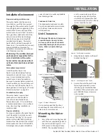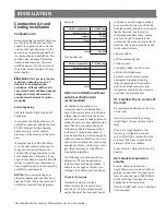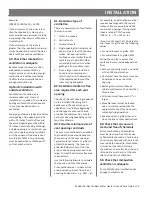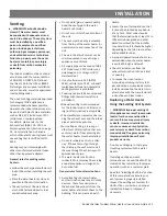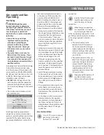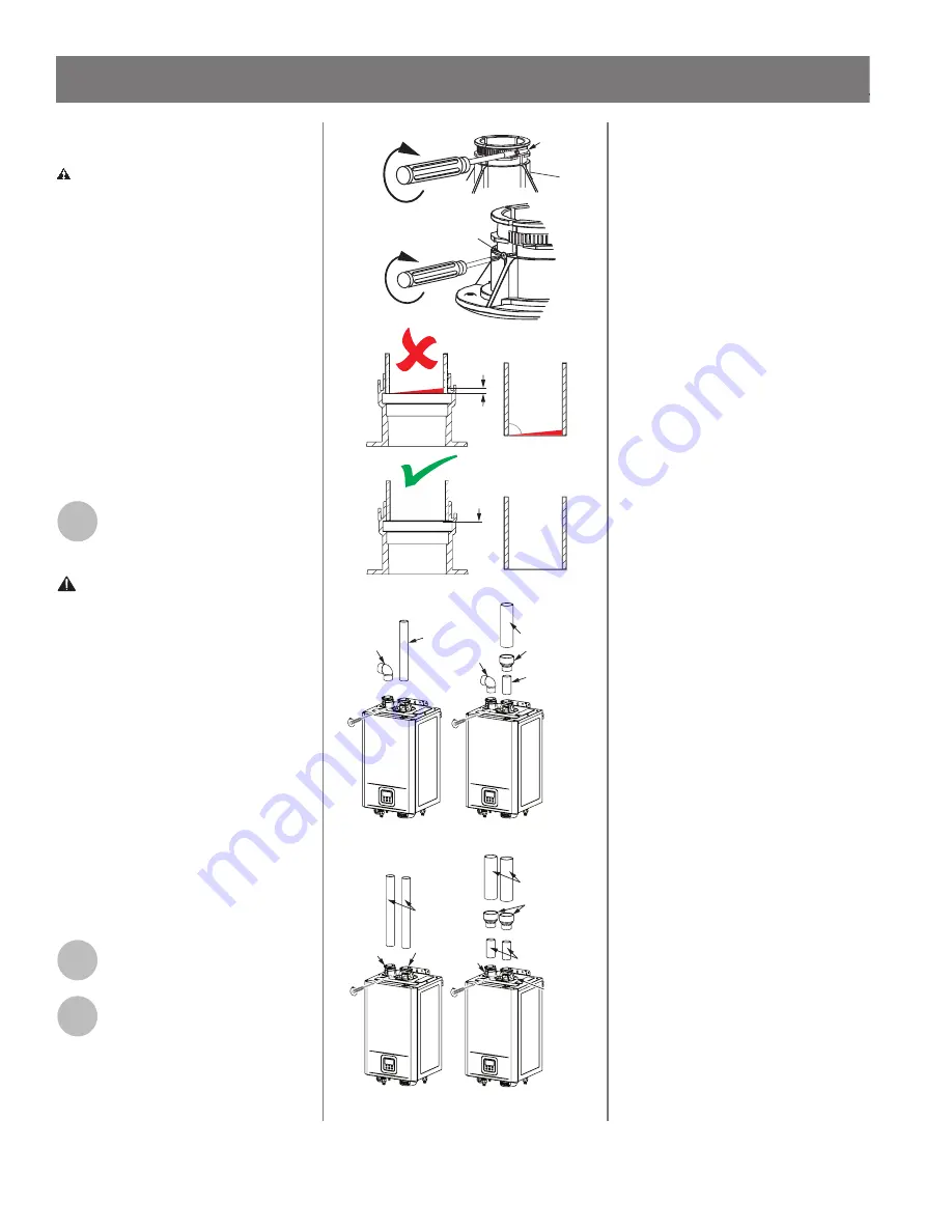
Installing the Vent Pipe.
WARNING! Improper installa on
can cause nausea or asphyxia on,
severe injury or death from carbon
monoxide and
fl
ue gases poisoning.
Improper installa on will void
product warranty
• When inser ng the pipe into the
exhaust/intake port, make sure
that the pipe end is cut straight and
posi oned properly under the o-ring
to seal the connec on
fi
rmly.
• Improper ven ng of this appliance
can result in excessive levels of
carbon monoxide which can result in
severe personal injury or death.
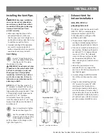
Vent Piping
1
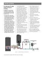
Insert 2" straight pipe fully
into the exhaust/intake ports.
(See Figure 15) The pipes
should insert 2 inches.
WARNING: The exhaust vent pipe
connec on to the water heater must
be
fl
ush to maintain a proper seal.
Check pipe for a 90° edge before
installa on. DO NOT use a
fi
eld cut
end for the connec on. Failure to
follow can cause carbon monoxide
poisoning or death.
NOTICE:
For 3” Ven ng, install a 2” x
3” increaser to convert to 3” ven ng.
For low clearance installa ons, a 2”
long sweep elbow may be used. Then
1 max length straight pipe may be
used to
fi
t a 2” x 3” increaser.
Air Intake for Power Vent Installs:
Insert the male end of a 2” or 3” long
sweep street elbow into the heater’s
air intake port.
2
Use a screwdriver to tighten
the clamp. (See Figure 15)
3
Use the supplied self-tapping
screws to secure the venting
to the intake and exhaust
ports as shown in the image on the
right. (See Figure 15)
Power Vent (PV)
Direct Vent (DV)
3” Pipe
2” to 3”
Adapter
2” Pipe
2” Pipe
3” Pipe
2” to 3”
Adapter
2” Pipe
2” Pipe
2” Pipe
2” Pipe
Pipe end
ŶŽƚŇƵƐŚ
ǁŝƚŚďĂƐĞ͘
Pipe end
ŝƐŇƵƐŚ
ǁŝƚŚďĂƐĞ͘
Not a
90° edge
džŚĂƵƐƚsĞŶƚ
Pipe
90° edge
džŚĂƵƐƚsĞŶƚ
Pipe
džŚĂƵƐƚ
Intake
Port
Intake Port
džŚĂƵƐƚ
Port
Clamp
Self-Tapping Screw
Figure 15 -
Vent Pipe Installa on
Exhaust Vent for
Indoor Installa on
ABS, PVC, CPVC or
polypropylene vent
The Indoor model can be vented with
ABS, PVC, CPVC, or polypropylene
(temperature rated up to 149°F).
In Canada, plas c ven ng must be
cer
fi
ed to ULC S636.
• The maximum length of exhaust
ven ng and intake piping shall not
exceed the lengths listed in Table 8.
• Do not use more than 5 elbows in a
vent system. 90 degree elbow add-
ed, deduct 5 . 45 degree elbows
count as 2.5 feet. If an elbow(s)
is used in the vent system, deduct
each equivalent length from the
Max. vent length to decide the total
vent length.
• When the horizontal vent run
exceeds 5 (1.5 m), support the
vent run at 3 (0.9 m) intervals with
overhead hangers.
• In areas of high rainfall the installa-
on of the rain trap may be neces-
sary.
• Slope horizontal ven ng sec ons
1/4" upwards for every 12" (305
mm) toward the termina on or
according to local and state codes,
or in the absence of local or state/
provincial codes, the current edi on
of the ANSI Z223.1/NFPA 54, Na on-
al Fuel Gas Code or B149.1, Natural
gas and propane installa on code.
Residen al Gas Tankless Water Heater Use and Care Guide • 23
INSTALLATION

