36 • Residen al Gas Tankless Water Heater Use and Care Guide
INSTALLATION
Combina on Potable
Water and Space
Hea ng
WARNING! This water heater
is suitable for combina on water
(potable) hea ng & space hea ng,
and not suitable for space hea ng
applica ons only.
•
This water heater shall not be
connected to any hea ng system
or component(s) previously used
with non-potable water where
any chemicals were added to the
water hea ng appliances.
•
Toxic chemicals used in boiler
treatments such as alcohol, glycer-
ol, and glycol groups must not be
introduced into the water system.
•
When the system requires water
for space hea ng at temperatures
higher than required for other
uses, thermosta c mixing valves
must be installed at each point-
of-use. Water temperatures over
125°F (52°C) can cause severe
burns instantly or death from
scalding. Failure to observe these
warnings could result in severe
personal injury or death.
Care must be taken by the installing
contractor or design engineer to
size the components of the system
appropriately for
fl
ow rate and
temperature. In addi on to sizing
the water heater for the domes c
potable water, the installer must size
the water heater to provide the
fl
ow
rate required by the manufacturer
of the air handler. Refer to the air
handler manufacturer’s instruc ons
and speci
fi
ca on documents for this
fl
ow rate. The pump,
fi
eld supplied
or provided by the air handler
manufacturer, must be able to
provide this minimum
fl
ow rate.
The water heaters internal
circula on pump shall not be used in
this applica on.
When sizing the pump, the installer
must take into account the pressure
drop of the following:
• Hydronic Air Handler. Refer to the
manufacturer for this informa on.
• Water Heater. Refer to the water
heater’s speci
fi
ca on sheet for
pressure drop informa on. At 3
gpm, the approximate head loss is
16.9 . of head (7.3 psi).
• Water Tubing Size, Length, and
Material. Refer to the water
tubing manufacture for pressure
drop informa on as it di
ff
ers
from one material to the next
and at di
ff
erent sizes. There
may be addi onal applica on
requirements by the water tubing
manufacturer.
• Fi ngs: Refer to the
fi
ng
manufacturer for pressure drop
informa on.
Addi onal considera ons are:
• Installing an air elimina on device
to remove air that may cause
cavita on in the pump.
• A priority control device, such
as a
fl
ow switch, to priori ze the
domes c water system over the
hea ng system.
• Thermosta c mixing valves at each
point-of-use. Refer to the mixing
valve manufacturer for proper
selec on and installa on.
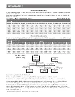
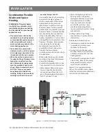
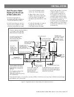
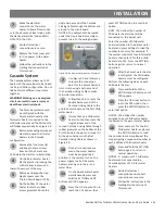
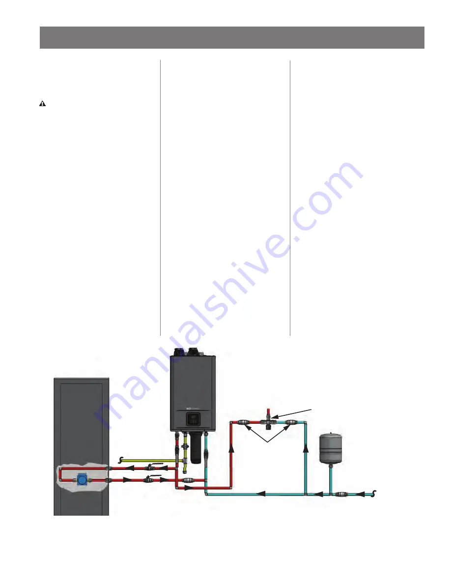
Figure 31 is a suggested piping
layout. The installer must properly
install the system per manufacturer’s
instruc ons and local codes.
GAS
AIR HANDLER
TEMPERED HOT
WATER TO FIXTURE
EXPANSION
TANK
COLD
WATER
SUPPLY
CHECK
VALVE
SHUT OFF
VALVE
PUMP
THERMOSTATIC MIXING
VALVE
CHECK
VALVE
Figure 31 -
Air Handler/Recircula on Loop Con
fi
gura ons

