Residen al Gas Water Heater Use and Care Guide • 65
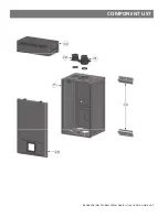
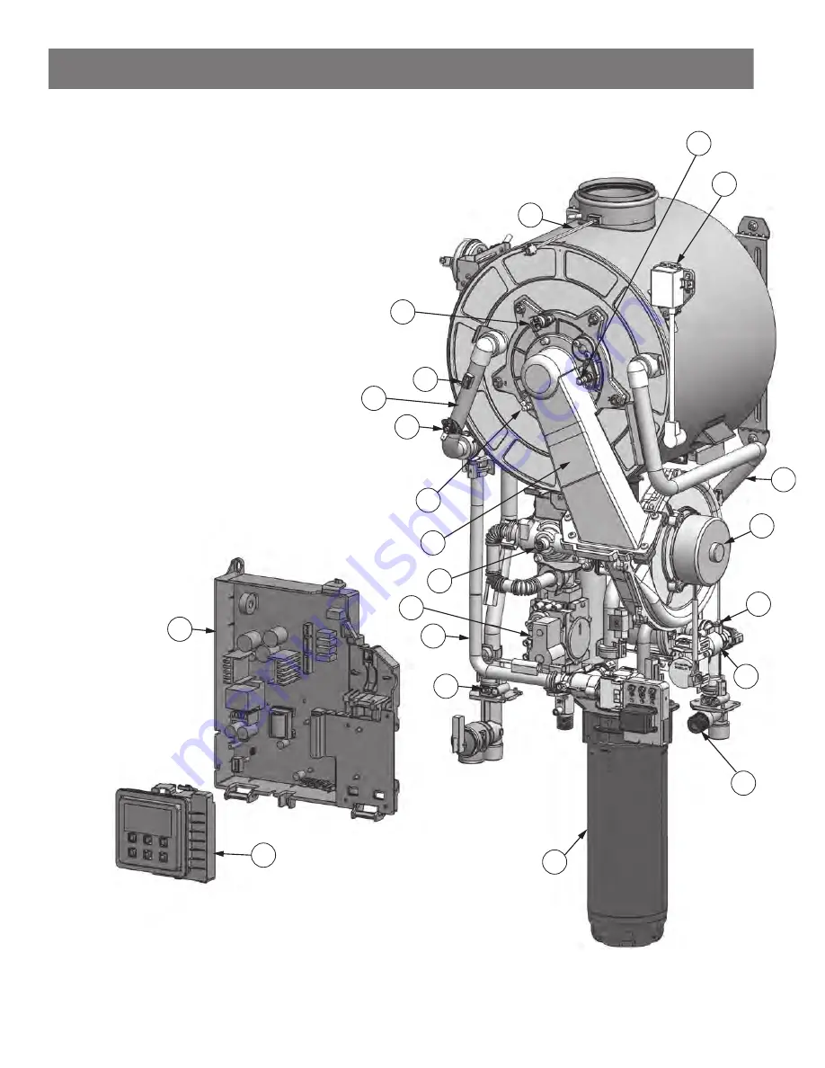
COMPONENT LIST
18
22
3
5
6
4
28
20
14
27
12
10
24
26
21
16
8
9
15
19
7
Page 1: ...risks including fire scalding electric shock and explosion causing serious injury or death Residen al Gas Tankless Water Heater Residen al On Demand Gas Tankless Water Heater X3 TECHNOLOGY available o...
Page 2: ...TED 12 Read Before Installa on 12 Included Items 14 Available Accessories 15 INSTALLATION 17 Installa on Environment 17 Unit Clearances 17 Moun ng the Water Heater 17 Combus on and Ven ng Installa on...
Page 3: ...FORE OPERATING 43 Temperature Adjustment 46 Unit Conversion Mode 47 Configura on Mode A Mode 48 Configura on Mode C Mode 48 Se ng the Clock 49 Se ng Recircula on Modes 50 Se ng the Pump Timers 52 Pump...
Page 4: ...protec on comes from the special X3 Cartridge media The X3 Cartridge must be installed into the manifold located on the underside of the heater cabinet prior to opera on of the unit X3 Scale Preven on...
Page 5: ...Tank Outlet Venting Inlet Air Pressure Relief Valve Drain Line not shown for clarity Water Shutoff Valve Water Shutoff Valve HWS CWS Drip Leg Gas Line Gas Shutoff Valve NOTE Condensate Drain not shown...
Page 6: ...2 00 cm 5 09 in 12 92 cm 6 70 in 17 00 cm 4 00 in 10 16 cm C L 12 28 in 31 20 cm 33 80 in 85 88 cm 3 73 in 9 47 cm Wall Water heater wall mount contact point 16 12 in 40 96 cm 8 31in 21 12 cm 5 08 in...
Page 7: ...ATER BASICS Table 1 Supply Connec ons Item DESCRIPTION MEASUREMENT CONNECTION SIZE 1 HOT OUTLET 9 00 in 23 cm 3 4 MNPT 2 GAS INLET 6 90 in 17 52 cm 1 2 MNPT 3 CONDENSATE 3 20 in 8 07 cm 1 2 MNPT 4 COL...
Page 8: ...0 3 24 Weight lbs kg 104 47 2 Dimensions including X3 inch W 16 54 x H 41 78 x D 16 12 cm W 42 00 x H 106 13 x D 40 96 Ignition Electronic Ignition Electric Supply 120V 50Hz 60Hz 5A Water Heater Cate...
Page 9: ...his odorant as an indica on of leaking gas We recommend installing a fuel gas and carbon monoxide detector This product is cer fied to comply with a maximum weighted average of 0 25 lead content DANGE...
Page 10: ...lumn Have a qualified person licensed plumber gas company personnel or authorized service technician check for proper L P gas pressure L P gas pressures exceeding 14 water column can result in serious...
Page 11: ...ce a flooded water heater Do not a empt to repair the unit It must be replaced Explosion Risk High pressures in the water heater can cause an explosion resul ng in property damage serious injury or de...
Page 12: ...s 248 CMR 2 00 and 248 CMR 5 00 State Plumbing Code Other local and state provincial authori es may have similar requirements or other codes applicable to the installa on of this water heater 3 Before...
Page 13: ...hbors Make sure the vent termina on meets the required clearance from any doorway or opening to prevent exhaust from entering a building Check local code requirements prior to installa on Vent termina...
Page 14: ...ector Included Items Table 4 Items Included with your Water Heater Item Descrip on Manual Installa on Instruc ons and Use Care Guide Pressure Relief Valve Pressure Relief Valve rated up to 150 psi and...
Page 15: ...Module or On Demand Receiver P N 100371899 for 10 3 m P N 100371900 for 32 10 m Remote Recircula on Kit Remote Recircula on Kit engages heater and recircula on at a touch of a bu on for on demand hot...
Page 16: ...ap Kit Outdoor Installa on Kit containing the outdoor vent cap and User Interface P N 100369060 Crossover Valve Kit Crossover valve for recircula on systems without a dedicated return line The kit inc...
Page 17: ...nal Fuel Gas Code in the United States and or Sec on 8 of the B149 1 Natural gas and propane installa on code in Canada as well as applicable local building codes Condensate Drain line The condensate...
Page 18: ...ide the house outdoor air is usually needed because modern homes are very ghtly sealed and o en do not supply enough air to the water heater However when installed in a large indoor space it may be po...
Page 19: ...nces in the space use your calcula on from Before Beginning and the type of vent used Table 6 provides the minimum free area for each vent opening depending on the type of ven la on B3 Calculate minim...
Page 20: ...nent Openings for Ven la on and Combus on Air Supply Air from outdoor or indoor spaces Based on the total BTU hr input ra ng for all gas burning appliances within a confined space Opening Source Minim...
Page 21: ...hermal insula on is prohibited Sidewall ven ng is recommended for the Indoor model Ver cal vent ing roof termina on is acceptable The manufacturer recommends run ning the exhaust vent and the intake p...
Page 22: ...lsulfone in non metallic ven ng systems is prohibited Covering non metallic vent pipe and fi ngs with thermal insula on is prohibited NOTE Approved vent and air intake Polypropylene vent materials Cen...
Page 23: ...ng screws to secure the venting to the intake and exhaust ports as shown in the image on the right See Figure 15 Power Vent PV Direct Vent DV 3 Pipe 2 to 3 Adapter 2 Pipe 2 Pipe 3 Pipe 2 to 3 Adapter...
Page 24: ...lla on Example Horizontal Installation Hanger Roof flashing Fire stop VerticalInstallation Figure 16 Vent Configura ons for Direct Vent Power Vent Installa on Examples Horizontal Installation Hanger V...
Page 25: ...rt Number IPEX System 1738 PVC Part Number 2 100187903 196984 397984 3 100187887 196985 397985 CONCENTRIC TERMINATION B A C A B C FGV 2 29 16 2 FGV 3 36 20 3 Vent Pipe Size PVC Kit Number IPEX PVC Par...
Page 26: ...otherm Part Number 2 ISTT0220 3 ISTT0320 POLYPROPYLENE RADIUS ELBOWS VentPipeSize Centrotherm Part Number 2 45 EXHAUSTELBOW ISELS0245UV 3 45 EXHAUSTELBOW ISELS0345UV 2 87 INLETELBOW ISELS0287UV 3 87 I...
Page 27: ...ance of 15 ft 4 5 m J Clearance to non mechanical air supply inlet to a building or the combustion air inlet to any other appliance 3 ft 91 cm 1 ft 30 cm 4 ft 1 2 m below or to side of opening 1 ft 30...
Page 28: ...st be at least 1 305 mm from other DV termi na ons 2 610 mm from an inside corner Inside corner 610mm min 305mm min 305mm min Combined Figure 19 Mul ple DV Sidewall Termina ons Exhaust and or direct v...
Page 29: ...as local and provincial codes Contact your local code enforcement agency for direc on Exhaust termina ons must be at least 1 305 mm away from any obstruc ons Minimum spacing between mul ple terminals...
Page 30: ...d keep the 3 screws securing it to the base of the water heater The plate is color coded and it should be rotated so that the yellow side of the plate is rotated up Secure with the screws removed earl...
Page 31: ...may adversely a ect the performance of the water heater These pres sures are measured when the water heater and any other gas appliance served by the same gas line are in full opera on Inlet gas press...
Page 32: ...67 393 315 267 237 217 196 185 173 162 146 132 112 1 1 071 732 590 504 448 409 378 346 322 307 275 252 213 1 1 4 2 205 1 496 1 212 1 039 913 834 771 724 677 630 567 511 440 1 1 2 3 307 2 299 1 858 1 5...
Page 33: ...union We recommend using a di electric type union available at your local plumbing supplier Dielectric unions can help prevent corrosion caused by ny electric currents common in copper water pipes an...
Page 34: ...wireless push bu ons A Remote Recircula on Kit is required see Available Accessories on page 15 This kit consists of one receiver wired to the water heater and at least one push bu on The receiver ca...
Page 35: ...d piping diagram Check with local codes and ordinances for addi onal installa on requirements Refer to the water heater manufacturer s website for addi onal layouts Thermosta c mixing valves may be us...
Page 36: ...s flow rate The pump field supplied or provided by the air handler manufacturer must be able to provide this minimum flow rate The water heaters internal circula on pump shall not be used in this appl...
Page 37: ...ot water outlet Check valve Electronically controlled every 6 hours for 60 seconds Wire to product approved pump used with air handler Cold water supply Discharge must comply with local and state code...
Page 38: ...ge into manifold and secure with the two long screws and one short screw previously set aside in Step 2 NOTICE The X3 cartridge is keyed to only install in one direc on Align the on the cartridge with...
Page 39: ...of 150 psi 1 MPa Condensate Drain Follow all code requirements of the local authority on condensate neu tralizers and whether or not they are required for the installa on Discharge condensate acidic...
Page 40: ...ust be electrically grounded Do not attach the ground wire to either the gas or the water piping 2 The water heater requires a 120 VAC 60 Hz electrical power supply that is properly grounded A proper...
Page 41: ...ascade Linking Cable to the printed circuit board on the first Child water heater 9 If more than one Child water heater is used then route the single harness end of the second Cascade Linking Cable th...
Page 42: ...Guide INSTALLATION Parent Unit Child Unit Child Unit Child Unit CWS HWS Gas Supply Building Return Cascade Linking Cable Parent Unit Child Unit Single Harness End Child Unit hild Unit Double Harness...
Page 43: ...a empt to repair the unit It must be replaced Start up Instruc ons Read and understand these direc ons thoroughly before a emp ng to start up the water heater Make sure the water is plumbed correctly...
Page 44: ...Figure 40 Ligh ng Instruc ons 44 Residen al Gas Tankless Water Heater Use and Care Guide OPERATION...
Page 45: ...Diagram Table 14 User Interface Display Item Descrip on A Water Flow Detected B Pump is Opera ng C Flame Detected D Pump Timer 1 2 Ac ve E Pump Bu on F Time Bu on G Up Down Bu ons H Opera on ON OFF Bu...
Page 46: ...ater temperature 3 Press the UP button to increase the water temperature WARNING Higher temperatures increase the risk of scalding but even at 120 F 50 C hot water can scald See Table 3 NOTE You can o...
Page 47: ...in Controller 1 Turn on the 120 VAC power supply to the water heater 2 Press the ON OFF bu on on the controller in order to turn the controller on 3 The set point temperature will display as shown in...
Page 48: ...C 5 10 default 15 20 25 30 35 3 6 default 8 11 14 17 19 A05 Recircula on Mode 0 1 No recircula on default Recircula on Ac ve A06 Recircula on Type 0 1 Dedicated Return Line default Crossover Valve A0...
Page 49: ...Descale Mode Se ng the Clock Table 19 Clock Se ng Set the Time on the Water Heater Built in Controller 1 Turn on the 120 VAC power supply to the water heater 2 Simultaneously Press and Hold the TIME...
Page 50: ...ased on the recircula on mode and ac va on deac va on modes a Set A06 to Press SETTING then press UP or DOWN to select the desired mode 0 for Recircula on with a Return Line 1 for Recircula on with a...
Page 51: ...rature goes below 100 F 38 C and deac vate when the inlet water temperature goes above 110 F 43 C 11 Press the UP bu on to go to mode A03 12 Press the SETTING bu on The display will alternate between...
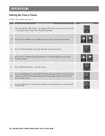
Page 52: ...the UP or DOWN arrow to change the hour to the desired ac va on me 3 Press the SETTING bu on to save the se ng and adjust the minute 4 Press the UP or DOWN arrow to adjust minute The ON se ng for Pum...
Page 53: ...on The Pump Timer 1 LED will display a er approximately 1 second This will indicate that Pump Timer 1 is ac vated 3 Press and release the TIME bu on to ac vate only Pump Timer 2 4 Press and release th...
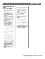
Page 54: ...nually check that it will discharge in a place for secure disposal The condensate drain system must be inspected regularly that it drains properly in accordance with local codes or the manufacturer s...
Page 55: ...water valve closed Keep the gas valve closed Keep supply power disconnected 8 To restore the unit to opera on reinstall the X3 Cartridge with 3 screws removed earlier 9 Open the cold inlet water valve...
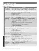
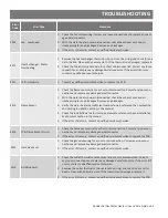
Page 56: ...splay when set to ON Is the gas supply valve open fully and within the allowable gas pressure range Is the water supply valve open fully Is the filter on the cold water inlet clean Is the hot water fi...
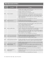
Page 57: ...er door tripped If the automa c Hi limit switch trip has occurred it cannot be reset and must be replaced Contact a qualified service technician E006 PCB Hardware Fault 1 Check PCB wiring for loose da...
Page 58: ...error may also appear when supply power has been turned back on In this case ignore the error code Reference Printed Circuit Board Ba ery on page 40 E049 Exhaust Thermistor Failure 1 Remove the thermi...
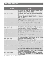
Page 59: ...e connector If the error s ll occurs contact a qualified service technician E385 Gas Valve SV1 1 The PCB detects an incorrect voltage from the gas valve solenoid valve 1 SV1 Correct any loose connec o...
Page 60: ...something else crea ng resistance Clear the blockage 5 Check to ensure the maximum pipe length and size has not been exceeded and meets the requirements in the Recircula on and Combina on Potable Wate...
Page 61: ...vent and air intake piping for any blockages Remove any blockages 3 Verify the water heater has su cient combus on air reference the Combus on and Ven ng Installa on sec on in the manual 4 Check the...
Page 62: ...s for a short or disconnec on Correct any loose connec ons and replace any damaged wire connector 2 Check the pressure tube for loose connec ons debris or blockages Correct any issue immediately 3 Wit...
Page 63: ...Correct any loose con nec ons and replace any damaged wire connector 4 Drain the water heater following Unit Draining Power Outage sec on in this manual 5 Remove the flow sensor and inspect for any d...
Page 64: ...64 Residen al Gas Water Heater Use and Care Guide COMPONENT LIST 1 18 22 3 20 4 6 21 28 14 25 13 2 7 12 34...
Page 65: ...Residen al Gas Water Heater Use and Care Guide 65 COMPONENT LIST 18 22 3 5 6 4 28 20 14 27 12 10 24 26 21 16 8 9 15 19 7...
Page 66: ...66 Residen al Gas Tankless Water Heater Use and Care Guide COMPONENT LIST 18 3 5 6 20 14 7 12 10 23 21 16 22 15 24...
Page 67: ...Residen al Gas Tankless Water Heater Use and Care Guide 67 COMPONENT LIST 29 17 32 31 30 33...
Page 68: ...COMPONENT LIST 68 Residen al Gas Tankless Water Heater Use and Care Guide...
Page 69: ...FILTER 11 BYPASS CARTRIDGE NOT SHOWN 12 X3 CARTRIDGE 13 OUTLET WATER TUBE 14 BYPASS WATER TUBE 15 HEAT EXCHANGER OUTLET WATER TUBE 16 INLET WATER TUBE 17 CASE FRONT COVER NOT SHOWN FOR CLARITY 18 EXHA...
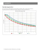
Page 70: ...r heater will de rate approximately 3 NG or 4 5 LP per 1 000 305 m of eleva on increase above 2 000 610 m 0 1 2 3 4 5 6 7 8 9 10 11 12 30 35 40 45 50 55 60 65 70 75 80 85 90 95 100 Flow Rate GPM THR F...
Page 71: ...NOTES Residen al Gas Tankless Water Heater Use and Care Guide 71...
Page 72: ...Copyright 2023 A O Smith All Rights Reserved...