30
Servicing should only be performed by a Quali
fi
ed Service Technician
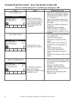
TROUBLESHOOTING CHART - FAULT MESSAGES DISPLAYED
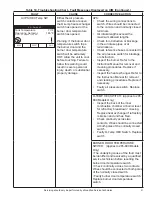
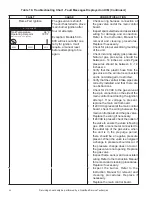
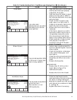
Table 10. Troubleshooting Chart - Fault Messages Displayed on UIM
FAULT
CAUSE
CORRECTIVE ACTION
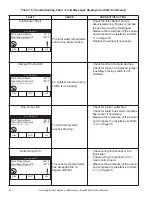
Gas Pressure SW
Either the manual reset
low gas pressure switch or
the manual reset high gas
pressure switch tripped
OR the swtiches are not
connected.
• Measure the supply gas pressure to
determine cause of failure. Natural
gas pressures should be between
4 - 14 inches w.c.
• Refer to the Instruction Manual for
detailed information concerning the
gas supply.
• Correct the supply gas pressure if
necessary.
• Reset the pressure switches.
• Check for a loose or misplaced
jumper if pressure switches are not
installed.
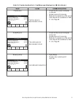
Flow Switch/ LWCO
The
fl
ow switch is not
closed when it should be.
• Check water heater pump operation
on a call for heat.
• Check for closed valves or
obstructions in the water heater
piping.
• Verify system is full of water and
all air has been purged from the
system.
• Check voltage to pump.
• Check pump relay operation.
• Check for disconnected wires to
pump.
• Check for disconnected wires to
fl
ow
switch.
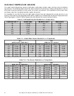
Blocked Condensate SW
The blocked condensate
switch has detected
excessive condensate build
up inside the unit.
• Check condensate tube from unit to
fl
oor drain for proper installation and
obstructions.
• Inspect condensate trap for
blockage. Clean if necessary.
• Check for loose wiring connection at
wire harness plug.
• Bad blocked condensate switch.
Replace switch.
Tank Temperature
70°F
Operating Setpoint
146°F
S t a t u s : G a s P r e s s u r e SW
HELP
RESET
A. O. Smith XP
MENU
Tank Temperature
73°F
Operating Setpoint
185°F
S t a t u s : F l o w S w i t c h / LW C O
HELP
RESET
A. O. Smith XP
MENU
Tank Temperature
74°F
Operating Setpoint
185°F
S t a t u s : B l o c k e d C o n d e n s a t e SW
HELP
RESET
A. O. Smith XP
MENU


