background image

4

A1-M-XL

1.  GENERAL INFORMATION

1.1  MANUFACTURER AND MACHINE IDENTIFICATION PLATE

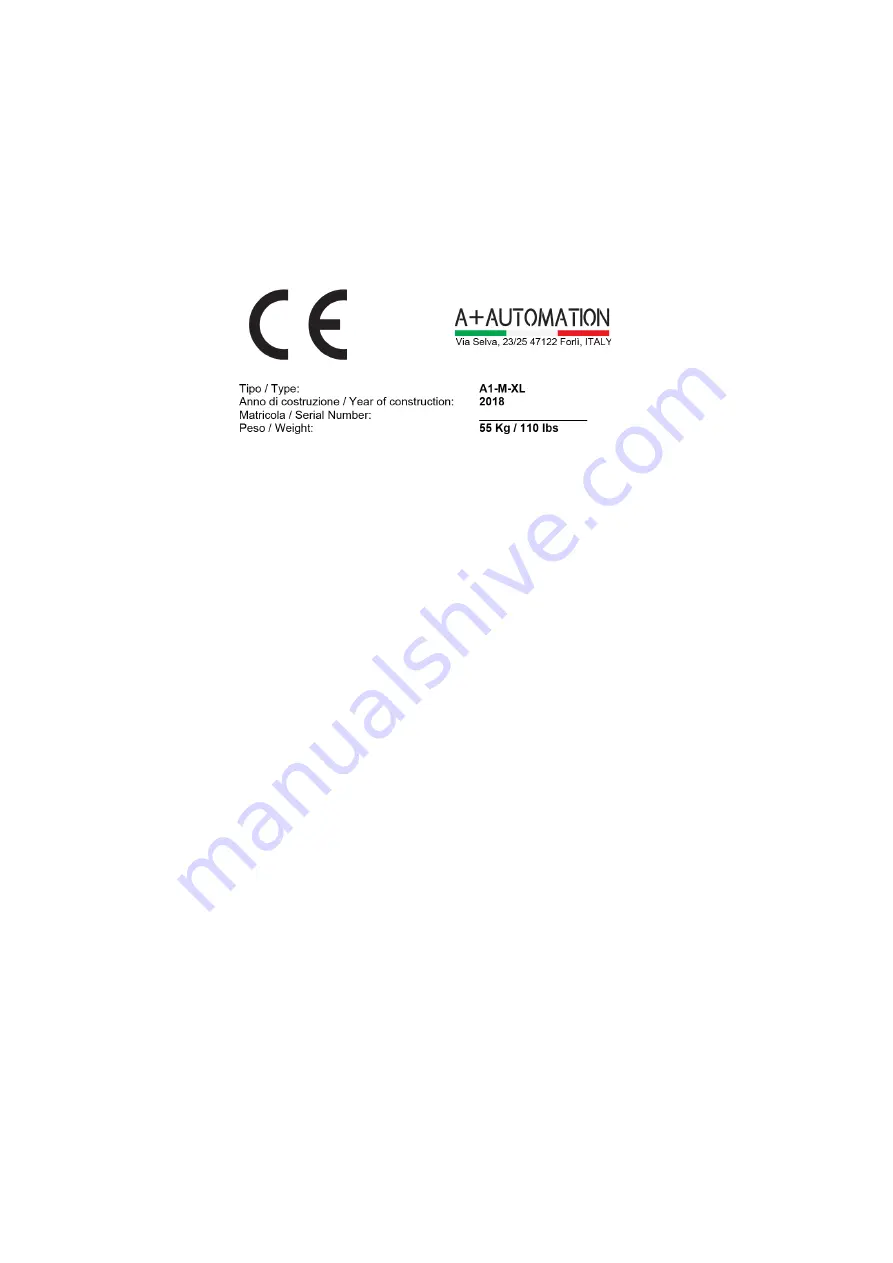
The identification plate illustrated is affixed directly on to the machine. The plate contains all identification details and

indications necessary for safe operation.

1.2  TECHNICAL SERVICE REQUEST PROCEDURES 

For any requirement, please contact the Manufacturer’s Customer Service.

For any request for technical service, list the data on the identification plate, the approximate number of hours the 

machinery has been used and the type of malfunction.

1.3 CERTIFICATION

The machine is produced in conformity to the pertinent European Community Norms in force at the moment of 

its introduction on the market.

1.4 WARRANTY

The replacement of defective parts is warranted (counting from the date written on the delivery bill) for a period of:

•  Mechanical components - 24 months

The driver blade is tested for more than 1.000.000 working cycles.

The Warranty does not include sending of technical staff. The repair will be performed at A-Plus Automation’s facility 

and the freight of shipment will be entirely charged to the Customer. The warranty does not cover the damages 

caused by an inappropriate use of the machine or not corresponding to the instructions described in this handbook.

The warranty decays in case of unauthorized modifications or because of accidental damages or tampering 

performed by unqualified personnel. The warranty also decays if you use wedges different from the original special 

steel A+ ones. To take advantage of warranty services it is necessary, at the moment you receive your machine to 

completely fill out the warranty card and send back as soon as possible to A-Plus Automation. The warranty will 

be valid after it is received & recorded at A-Plus Automation.

1.5  PRE-ARRANGEMENTS CHARGED TO THE CUSTOMER RESPONSIBILITY

It is the customer’s duty, on times agreed with the manufacturer, to execute what is indicated in our documentation.

Things normally charged to the customer:

•  Premises predisposition, included building works 

1.6  PURPOSE OF THE MANUAL

The manual herein, part and parcel with the machinery, has been designed and built by the manufacturer with the 

purpose to supply the necessary information to the persons authorized to operate the machinery during its useful life.

As well as adopting an appropriate utilization technique, the recipients of the information must read and strictly 

apply them. This information is supplied by the manufacturer in its own language (Italian) and may be translated 

into other languages to satisfy statutory and/or sales needs. A time dedicated to the study of this information, will

permit the user to avoid health and safety risks to personnel and economic loss. The translation in the language of 

the country of use, supplied by the manufacturer, its representative or whoever brings the machine to such linguistic 

area, must be carried out from the “ORIGINAL INSTRUCTIONS” and must display the phrase “TRANSLATION OF 

THE ORIGINAL INSTRUCTIONS”. In the event that the manual herein contains additional information concerning 

the fittings of the machinery, said information does not interfere with the reading of the manual.

Keep this manual for the entire duration of its useful life in a well known and easy to access place, available for 

reference any time the need should arise.

The manufacturer reserves the right to make modifications with no obligation to supply a prior notification.

Summary of Contents for A1-M-XL

Page 1: ...INSTRUCTION HANDBOOK A PLUS AUTOMATION s r l Via Selva 23 25 47122 Forl Italy Tel 39 0543 481142 Fax 39 0543 480770 info a plusautomation com www a plusautomation com A1 M XL...

Page 2: ...2 A1 M XL Table of Contents 1 GENERAL INFORMATION 4 3 SAFETY 8 4 INSTALLATION 9 5 FUNCTIONING 14 6 MAINTENANCE 16 7 DIAGNOSTIC 17 8 SPARE PARTS 18 9 DEMOLITION 18 10 ATTACHMENTS 18...

Page 3: ...3 A1 M XL...

Page 4: ...e warranty card and send back as soon as possible to A Plus Automation The warranty will be valid after it is received recorded at A Plus Automation 1 5 PRE ARRANGEMENTS CHARGED TO THE CUSTOMER RESPON...

Page 5: ...which if overlooked could put people s health and safety in great danger WARNING Indicates technical information of particular importance which must not be overlooked INQUIRY The user is requested to...

Page 6: ...of several types at quick replacement to have the proper clamping of any profile Manual opening of the nail magazine for a very quick reloading Nail heads sizes 7 10 and 15 mm 2 3 AXIS Z AXIS Movemen...

Page 7: ...mm Optional Wedge size 3mm 5mm 12mm Weight approx 50 kg 110 lbs Height of work bench 1000mm 39 Overall dimensions 400mm x 500mm x 1410mm 15 3 4 x 19 11 16 x 55 33 64 2 8 EQUIPMENT SUPPLIED The equipme...

Page 8: ...tor The lack of these requisites may jeopardize the safety and health of personnel During operation only use the personal protection clothes and or devices listed in the instructions supplied by the...

Page 9: ...ALLATION 4 1 HANDLING AND INSTALLATION The personnel in charge of loading unloading and moving the machinery must possess the skills and experience acquired and acknowledged in the specific sector and...

Page 10: ...LIMINARY ARRANGEMENTS To install the machine it is necessary to prepare a working area adequate to the machine s dimensions lifting devices chosen and length of mouldings to be worked 4 6 PRELIMINARY...

Page 11: ...w pusher by by releasing the nylon thread see Picture 7 Insert the new size Wedge guide head to match the Wedges to be used see pict 8 Tighten the locking screw of the Wedge guide head see pict 7 Pict...

Page 12: ...bar to allow its shifting forward or backward up to reach the pressure pad directly in line with Wedge inserting point Tighten the handle once reached the proper position Picture 12 4 8 2b Vertical cl...

Page 13: ...to the wedges size loaded in the magazine The adjustment of the vertical clamp is correct chapter 4 8 2 Pressing halfway down on the pedal the vertical clamp hold the frame properly The adjustment of...

Page 14: ...sition and holding 6 Press the pedal full down to insert the Wedge If you want to insert 2 or more Wedges one upon the other in the same position you must release the pedal until half of its stroke an...

Page 15: ...14 5 4 MACHINE STOP The machine can only work by pressing the mechanical foot pedal To stop it lift your foot from the pedal 5 5 MACHINE REINSTATEMENT The machine reinstatement is performed by pressin...

Page 16: ...the operations are finished replace any parts you removed or opened 6 4 CLEANING The machine structure is simple and robust therefore the mechanical parts do not require any special maintenance It is...

Page 17: ...ges one upon the other in the same point they do not stack properly or tilt during their insertion Unsuitable Wedges Replace the Wedges with suitable ones Poor frames clamping the frame moves during t...

Page 18: ...r of Technical Assistance which has access to qualified staff proper equipment and tools and who uses original spare parts To order the above spare parts send the following data by fax or letter Model...

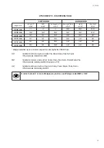
Page 19: ...HW Wedges available only on custumer s request for orders higher than 500 000 pcs SW Suitable for soft wood such as Cedar Pine Bass Banak Obeche Poplar Other materials Vertical Grain MDF MW Suitable...

Page 20: ...20 A1 M XL SCHEMES B Mechanic Schemes A1 M XL P R E L I M I N A R Y...

Page 21: ...21 A1 M XL SCHEMES B Mechanic Schemes A1 M...

Page 22: ...22 A1 M XL...

Page 23: ...23 A1 M XL...

Page 24: ......

Reviews: