6
A1-M-XL
2. MACHINE DESCRIPTION
2.1 WORKING PRINCIPLE
The manual Frame Assembling Machine A1-M-XL has been realized for the production of frames.
The A1-M-XL being of simple construction and extremely easy to use, makes it possible to join with absolute
precision any kind of moulding by using special steel A+ wedges to realize molding joints.
2.2 MAIN COMPONENTS
The main components constituting the machine are:
• Dual stage mechanical operating foot pedal that activate the vertical clamping device to allow a proper locking
of the mouldings and the nail insersion in different positions
• Magnetic pressure pads of several types, at quick replacement, to have the proper clamping of any profile
• Manual opening of the nail magazine for a very quick reloading
• Nail heads sizes 7, 10 and 15 mm.
2.3 AXIS
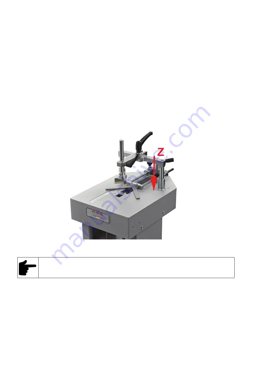
- Z AXIS
Movement of vertical clamp.
Picture 2. 1 A - Movement directions
2.4 AMBIENT CONDITIONS IN THE INSTALLATION AREA
The installation area must have adequate environmental conditions.
The installation area must meet the following requisites.
• Adequate lighting to European standards (recommended 250÷650 lux)
• Well ventilated rooms
• Adequate relative humidity and temperature. The permitted temperatures go from 5° to 40° C, with a humidity
level not higher than 50% at 40° C or 90% at 20° C.
• The floor, as well as having an adequate load capacity for the machine weight, must be stable and levelled in
order to guarantee a correct support.
Summary of Contents for A1-M-XL
Page 3: ...3 A1 M XL...
Page 20: ...20 A1 M XL SCHEMES B Mechanic Schemes A1 M XL P R E L I M I N A R Y...
Page 21: ...21 A1 M XL SCHEMES B Mechanic Schemes A1 M...
Page 22: ...22 A1 M XL...
Page 23: ...23 A1 M XL...
Page 24: ......


