background image

9

A1-M-XL

3.5  SAFE WORKING PROCEDURES

The machine is projected and realized to eliminate any risk connected with its use.

The user is requested to achieve an adequate training to be instructed by their distributor.

The other risks related with working are:

•  Finger crushing in the vertical clamp working area

It is necessary to carefully adhere to the following instructions:

•  Keep the fingers away from vertical clamp working area

•  Keep the foot away from the pedal during machine maintenance.

3.5  RESIDUAL RISKS

During the normal working cycle and while maintenance, the operators are exposed to several residual risks that, 

because of operations own nature, can not be totally eliminated.

•  Risk of finger crushing due to the presence of vertical clamping

4. INSTALLATION

4.1  HANDLING AND INSTALLATION

The personnel in charge of loading, unloading and moving the machinery must possess the skills and experience 

acquired and acknowledged in the specific sector, and must thoroughly know the lifting means to be employed. 

The machine has to be shipped in a safe way to avoid any damage to its parts.

•  All the protections and guard devices must be properly closed and locked.

•  According to the type of shipment, it is necessary to protect the machine from any jarring impact or stress 

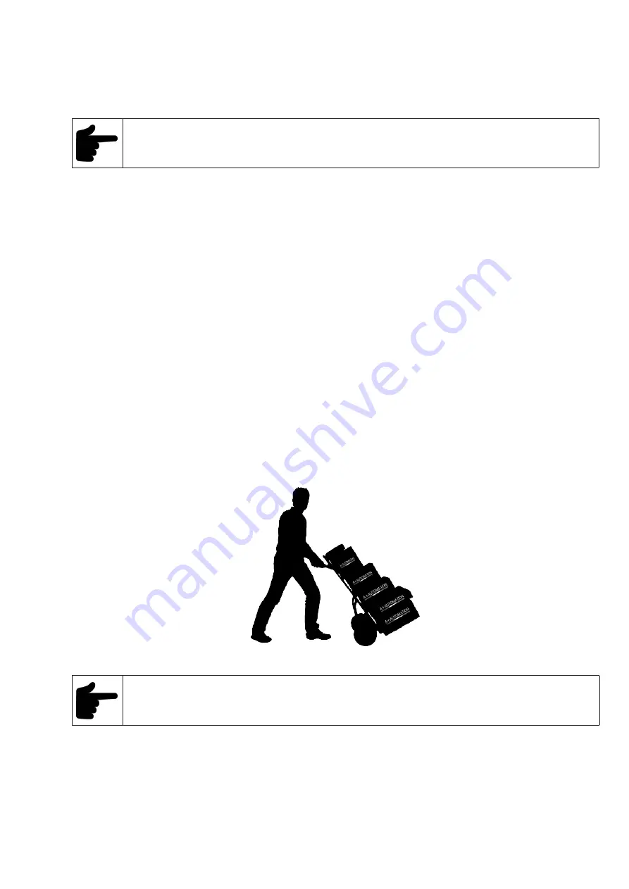
Picture 4.1A – machine handling indications

Machine total weight: about 50 Kilos / 110 lbs

 Lifting must be done by using a specific device.

4.2  WAREHOUSING AND STORAGE PROCEDURES 

•  In order to avoid that the components cause dangers or are damaged, the storage area must be covered 

(preferably a closed area) and accessible only for authorised personnel.

•  Avoid corrosive materials that could touch the machine

•  Lubricate the parts which are not painted

Summary of Contents for A1-M-XL

Page 1: ...INSTRUCTION HANDBOOK A PLUS AUTOMATION s r l Via Selva 23 25 47122 Forl Italy Tel 39 0543 481142 Fax 39 0543 480770 info a plusautomation com www a plusautomation com A1 M XL...

Page 2: ...2 A1 M XL Table of Contents 1 GENERAL INFORMATION 4 3 SAFETY 8 4 INSTALLATION 9 5 FUNCTIONING 14 6 MAINTENANCE 16 7 DIAGNOSTIC 17 8 SPARE PARTS 18 9 DEMOLITION 18 10 ATTACHMENTS 18...

Page 3: ...3 A1 M XL...

Page 4: ...e warranty card and send back as soon as possible to A Plus Automation The warranty will be valid after it is received recorded at A Plus Automation 1 5 PRE ARRANGEMENTS CHARGED TO THE CUSTOMER RESPON...

Page 5: ...which if overlooked could put people s health and safety in great danger WARNING Indicates technical information of particular importance which must not be overlooked INQUIRY The user is requested to...

Page 6: ...of several types at quick replacement to have the proper clamping of any profile Manual opening of the nail magazine for a very quick reloading Nail heads sizes 7 10 and 15 mm 2 3 AXIS Z AXIS Movemen...

Page 7: ...mm Optional Wedge size 3mm 5mm 12mm Weight approx 50 kg 110 lbs Height of work bench 1000mm 39 Overall dimensions 400mm x 500mm x 1410mm 15 3 4 x 19 11 16 x 55 33 64 2 8 EQUIPMENT SUPPLIED The equipme...

Page 8: ...tor The lack of these requisites may jeopardize the safety and health of personnel During operation only use the personal protection clothes and or devices listed in the instructions supplied by the...

Page 9: ...ALLATION 4 1 HANDLING AND INSTALLATION The personnel in charge of loading unloading and moving the machinery must possess the skills and experience acquired and acknowledged in the specific sector and...

Page 10: ...LIMINARY ARRANGEMENTS To install the machine it is necessary to prepare a working area adequate to the machine s dimensions lifting devices chosen and length of mouldings to be worked 4 6 PRELIMINARY...

Page 11: ...w pusher by by releasing the nylon thread see Picture 7 Insert the new size Wedge guide head to match the Wedges to be used see pict 8 Tighten the locking screw of the Wedge guide head see pict 7 Pict...

Page 12: ...bar to allow its shifting forward or backward up to reach the pressure pad directly in line with Wedge inserting point Tighten the handle once reached the proper position Picture 12 4 8 2b Vertical cl...

Page 13: ...to the wedges size loaded in the magazine The adjustment of the vertical clamp is correct chapter 4 8 2 Pressing halfway down on the pedal the vertical clamp hold the frame properly The adjustment of...

Page 14: ...sition and holding 6 Press the pedal full down to insert the Wedge If you want to insert 2 or more Wedges one upon the other in the same position you must release the pedal until half of its stroke an...

Page 15: ...14 5 4 MACHINE STOP The machine can only work by pressing the mechanical foot pedal To stop it lift your foot from the pedal 5 5 MACHINE REINSTATEMENT The machine reinstatement is performed by pressin...

Page 16: ...the operations are finished replace any parts you removed or opened 6 4 CLEANING The machine structure is simple and robust therefore the mechanical parts do not require any special maintenance It is...

Page 17: ...ges one upon the other in the same point they do not stack properly or tilt during their insertion Unsuitable Wedges Replace the Wedges with suitable ones Poor frames clamping the frame moves during t...

Page 18: ...r of Technical Assistance which has access to qualified staff proper equipment and tools and who uses original spare parts To order the above spare parts send the following data by fax or letter Model...

Page 19: ...HW Wedges available only on custumer s request for orders higher than 500 000 pcs SW Suitable for soft wood such as Cedar Pine Bass Banak Obeche Poplar Other materials Vertical Grain MDF MW Suitable...

Page 20: ...20 A1 M XL SCHEMES B Mechanic Schemes A1 M XL P R E L I M I N A R Y...

Page 21: ...21 A1 M XL SCHEMES B Mechanic Schemes A1 M...

Page 22: ...22 A1 M XL...

Page 23: ...23 A1 M XL...

Page 24: ......

Reviews: