background image

16

A3-P

5. OPERATING MODES

5.1 OPERATORS

The machine has been designed to be used by only one operator.

The operator, as well as being adequately informed on the use of machinery, must possess skills and competence 

adequate to the type of work to be performed.

Even after being adequately informed, during the first use, if necessary, simulate some operating maneuvers to 

identify the controls, especially the ones for starting and stopping the machinery and their main functions.

How to operate in case of emergency , where to find the individual protection means and how to use them properly.

5.2  DESCRIPTION OF FUNCTIONS

The machine has only one possible operating mode: Manual operation by using the pneumatic foot pedal.

Press the foot pedal half way down to clamp the frames

Press the foot pedal all the way down to drive a wedge.

To assemble a frame  junction, you must operate as follows:

1.  Set the inserting positions by means of the fence locking clamps

2.  Place the moulding on the work bench. Move the fence to the first inserting point.

3.  Adjust the vertical clamp height and position

4.  Adjust the frontal clamp position

5.  Verify and  adjust the proper working pressure, using the pressure regulator, according to the type of moulding 

to be assembled are the mouldings to be assembled.

6.  Press half way down on the pneumatic pedal to verify the proper position and clamping of the moulding. 

7.  Press the pedal all the way down to insert the Wedge. If you want to insert 2 or more Wedges, one upon the 

other in the same position, you must release the pedal halfway and then press it all the way down again to 

insert the second Wedge and so on.

8.  Completely release the foot pedal

9.  (If the assembly requires it) Move the moulding and the fence to the next inserting point and repeat the steps 

6,7 and 8.

5.3  TIPS FOR QUALITY JUNCTIONS
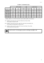
a)  Wedge types

In order to allow the machine to make excellent quality joints using different materials, it has been necessary to 

manufacture different Wedges types for different uses (see attachment D).

Wedges can be classified in three different groups:

Material

Suggested code

Color Ref. 

soft materials (wood, soft plastic)

SW

Green

for medium materials (wood, ...)

MW

Gray

for hard materials (wood, MDF, HDF)

HW

Red

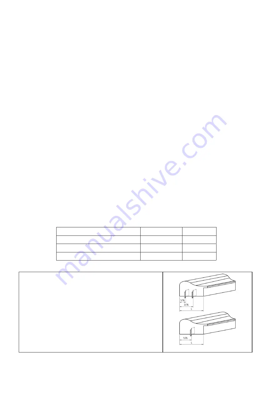
b)  Assembling positions

It is advisable to operate as follows in order to achieve the best results in terms of junction quality:

•   Never drive Wedges near the external vertex. The minimum 

recommended distance from the external vertex is at least 10 mm.

•   When you want to make the junction using only one Wedge, the 

most suitable position is in the middle of the moulding (see fig. 21)

•   In case you want to insert 2 or more Wedges into each junction, 

we recommend you to insert the most external one 1/3 from the 

external vertex and the most internal one 1/4 from the internal 

vertex (not less than 5mm).

picture 21

Summary of Contents for A3-P

Page 1: ...INSTRUCTION HANDBOOK A PLUS AUTOMATION s r l Via Selva 23 25 47122 Forl Italy Tel 39 0543 481142 Fax 39 0543 480770 info a plusautomation com www a plusautomation com A3 P...

Page 2: ...INDEX 1 GENERAL INFORMATION 4 2 MACHINE DESCRIPTION 6 3 SAFETY 8 4 HANDLING AND INSTALLATION 9 5 OPERATING MODES 16 6 MAINTENANCE 17 7 DIAGNOSTIC 18 8 SPARE PARTS 19 9 MACHINE DEMOLITION 19 10 ATTACHM...

Page 3: ...3 A3 P...

Page 4: ...send back as soon as possible to A Plus Automation The warranty will be valid after it is received recorded at A Plus Automation 1 5 PRE ARRANGEMENTS CHARGED TO THE CUSTOMER RESPONSIBILITY It is the...

Page 5: ...hich if overlooked could put people s health and safety in great danger WARNING Indicates technical information of particular importance which must not be overlooked INQUIRY The user is requested to c...

Page 6: ...pening of the Wedge magazine for a very quick reloading Wedge heads sizes 7 10 and 15 mm 2 3 AXIS X AXIS Movement horizontal Y AXIS Movement vertical Picture 2 3 A Movement directions 2 4 AMBIENT COND...

Page 7: ...stance TABLE 2 7 A Tecnical data Frames thickness min max 8 100 mm 1 4 4 1 4 Frames width min max 6 150 mm 1 4 6 Wedges magazine capacity n 200 Wedges size 7 10 15 mm Wedges size on request 3 5 12 mm...

Page 8: ...ration only use the personal protection clothes and or devices listed in the instructions supplied by the manufacturer and the ones provided for by current regulations on safety at work During the nor...

Page 9: ...ng any maintenance interventions 3 Keep the foot away from the pedal during machine maintenance 3 8 DESCRIPTION OF SAFETY SIGNS Some of these signals are applied on the machine Their meaning is specif...

Page 10: ...ssembling machines must be positioned on a solid and leveled plane able to sustain the weight of the machine The bench must be studied and prepared by the customer and or qualified staff 4 5 PNEUMATIC...

Page 11: ...amaged Verify the pipes integrity 4 7 MACHINE ARRANGEMENT 4 7 1 Wedges magazine loading To load the wedge magazine proceed as follows Move the claw pusher backwards by flipping the special lever locat...

Page 12: ...see figure 7 Insert the new size wedge guide head to match the wedges you will be using see fig 11 Tighten the locking screw of the wedge guide head see fig 10 Picture 10 Picture 11 4 8 ADJUSTMENTS 4...

Page 13: ...ll the way down on the foot pedal to drive the wedge into the laths Picture 16 4 8 3 Horizontal clamp adjustment The horizontal clamp has a series of holes in the flat bar see fig 17 Lift the bar to t...

Page 14: ...ng 2 or more Wedges in the same position increase the working pressure by 20 4 8 5 Protective shield adjustment Machine is equipped with a protective shield made of transparent plastic material see fi...

Page 15: ...tective shield is properly positioned see chapter 4 8 5 The working pressure is adequate to the wood hardness see chapter 4 8 4 The mouldings to be assembled are properly positioned on the work bench...

Page 16: ...umatic pedal to verify the proper position and clamping of the moulding 7 Press the pedal all the way down to insert the Wedge If you want to insert 2 or more Wedges one upon the other in the same pos...

Page 17: ...quire any special maintenance Keep the machine in maximum efficiency conditions and perform all the scheduled maintenance operations provided by the manufacturer Good maintenance will result in better...

Page 18: ...e the control valves Pressing the foot pedal for several times the machine s working cycle that was correct at the beginning becomes irregular later Jammed valves because of surplus of oil or condensa...

Page 19: ...SPARE PARTS ORDERING We remind you that only a qualified technician can repair the machine Therefore we suggest the intervention of your local distributor or A Plus Automation Center of Technical Assi...

Page 20: ...zione Assemblatrice pneumatica per cornici e telai Modello A3 Tipo A3 P Matricola A3 18 xxxx Anno di costruzione 2018 risulta in conformit a tutte le diposizioni pertinenti previste dalle seguenti dir...

Page 21: ...de name A3 P Funzione Pneumatic frame assembling machine Model A3 Type A3 P Serial Number A3 18 xxxx Year of manufacture 2018 conforms with all provision applicable under the following EU Directives i...

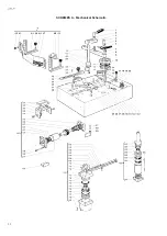
Page 22: ...22 A3 P SCHEMES A Mechanical Schematic...

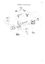
Page 23: ...23 A3 P SCHEMES B Pneumatic Schematic...

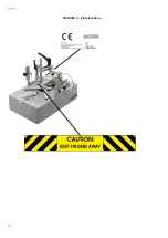
Page 24: ...24 A3 P SCHEME C Plate locations...

Page 25: ...s available only on customer s request for specific order quantities to be confirmed SW Suitable for soft wood such as Cedar Pine Bass Banak Obeche Poplar Other materials Vertical Grain MDF MW Suitabl...

Page 26: ...26 A3 P...

Page 27: ...27 A3 P...

Page 28: ...The company reserves the right to make changes to the products illustrated in this document at any time without notice...

Reviews: