11
A44-P
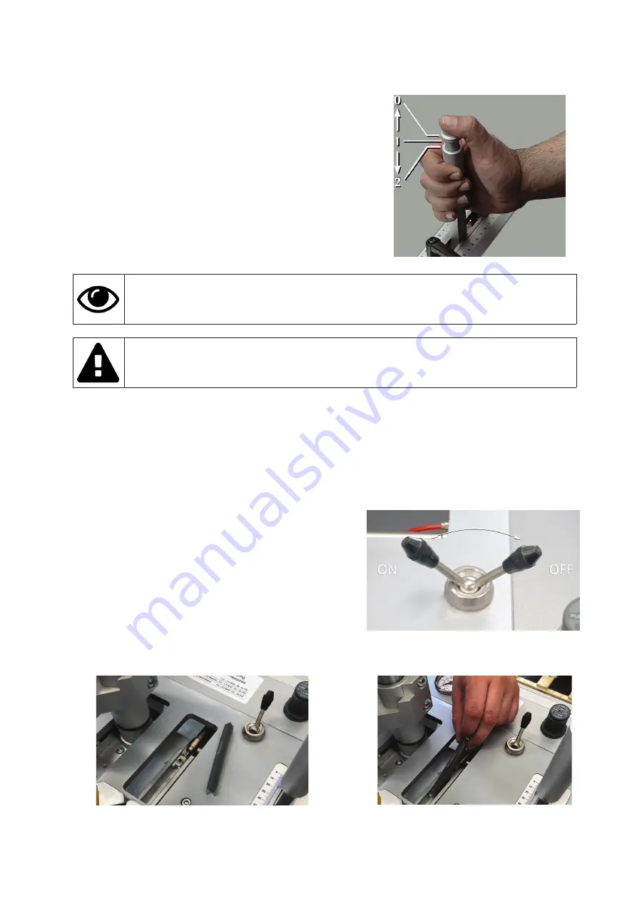
The manual control lever with 2 positions button activates the following
commands:
• Pressing the foot pedal it activates the locking of the horizontal clamp;
• Pressing pushbutton half-way down, it activates the vertical clamp
and the position brake;
• The Pushbutton pressed full down activates the wedge driving.
Check that pressure value showed on the pressure dial (B) of the lubricator/reducer filter is between
6 and 8 Bar (see picture 5)
DO NOT adjust by using the A regulator of lubricator/reducer filter (see 4.6.1.1)
4.6 PRELIMINARY CONTROLS
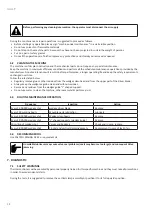
Before setting up the machine, execute checks to prevent mistakes or accidents during setup.
• Verify that machine has not been damaged.
• Verify the pipes integrity
4.7 MACHINE ARRANGEMENT
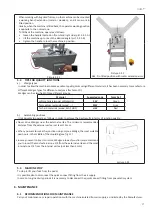
4.7.1 Wedges magazine loading
To load the wedge magazine proceed as follows:
• Move the claw pusher backwards by flipping the special
lever located on the right side of the machine working
bench. This will give you access to the nail magazine (see
pict. 4.7.1.1).
Picture 4.7.1.1
• Insert one or more nail strips into the magazine. Make sure that the sharpened edge of the nails (glue side) faces up and
that they are loaded with the V of the nails pointing in the direction indicated in the figures 4.7.1.2 and 4.7.1.3. Check to
see if the nail size is suitable with the type of claw head mounted.
Picture 4.7.1.2
Picture 4.7.1.3
• Move the claw pusher forward by flipping the control lever (see pict. 4.7.1.1)
Summary of Contents for A44-P
Page 3: ...3 A44 P...
Page 21: ...21 A44 P...
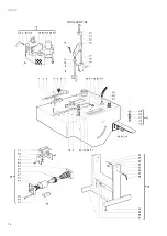
Page 24: ...24 A44 P DWG A44 P 01...
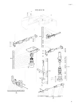
Page 25: ...25 A44 P DWG A44 P 02...
Page 26: ...26 A44 P SCHEMES B Pneumatic Scheme...
Page 27: ...27 A44 P...
Page 28: ...28 A44 P SCHEME C Plates location...
Page 30: ...30 A44 P...
Page 31: ...31 A44 P...
Page 32: ......


