background image

13

A44-P

4.8 ADJUSTMENTS

The machine has been completely tested and checked in Alfa Automation plants before its shipment. All the operator 

has to do is perform the following adjustments:

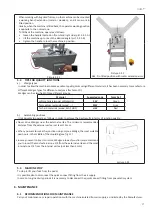
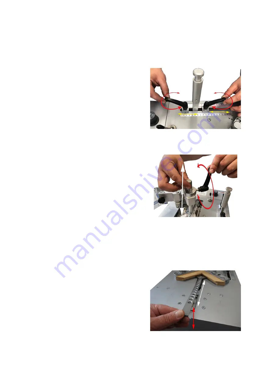
4.8.1  Setting stops for Wedges positioning

The working stroke of the driver blade is adjusted by 2 stop 

handles positioned on a measurement gauge (see fig. 4.8.1).

The stop located inside the hand lever (operator side), refers 

to the Wedges rear position; the located in front of a.m. lever 

refers to the Wedges external position.

The carriage with the driver blade is positioned by shifting the 

handle from the eternal position to the rear one.

Picture 4.8.1

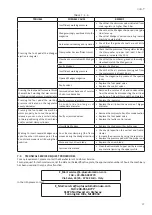
4.8.2  Vertical clamp adjustment

The vertical clamp position can be adjusted by the side-handle. Proceed as follows to position properly the vertical clamp:

•  Loosen the side clamp (see picture 4.8.2.1) by using the 

handle and adjust the pressure pad height over the frame 

(it is advisable to adjust an height between 5 and 8 mm 

to avoid any accidental fingers crushing).

•  Tighten the handle once reached the proper position

•  Activate the vertical clamp by pressing half way the foot 

pedal and then the control button or pressing full down 

the full pedal.

•  Check that the mouldings to be assembled are properly 

clamped.

Picture 4.8.2.1

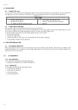
4.8.3  Horizontal clamp adjustment

The Frontal Clamp (horizontal clamp) has a series of holes in the flat bar (see Pict. 4.8.3.1) that lock into a peg in the 

front channel. Lift the bar to take it out of its initial position and make it move forward and backward.

To lock the bar it is sufficient to insert it into the proper peg located at the centre of the guide channel.

Proceed as follows to position the Horizontal Clamp correctly:

•  Remove the bar from the peg (lifting it by about 10-15 

mm) and move it forward up to reach the mouldings to 

be assembled;

•  Lower the bar to allow the insertion of tracking screw 

and the locking in the next position.

Picture 4.8.3.1

Summary of Contents for A44-P

Page 1: ...INSTRUCTION HANDBOOK A PLUS AUTOMATION s r l Via Selva 23 25 47122 Forl Italy Tel 39 0543 481142 Fax 39 0543 480770 info a plusautomation com www a plusautomation com A44 P...

Page 2: ...INDEX 1 GENERAL INFORMATION 4 2 MACHINE DESCRIPTION 6 3 SAFETY 8 4 HANDLING AND INSTALLATION 9 5 OPERATING MODES 16 6 MAINTENANCE 17 7 DIAGNOSTIC 18 8 SPARE PARTS 20 9 MACHINE DEMOLITION 20 10 ATTACHM...

Page 3: ...3 A44 P...

Page 4: ...A ones To take advantage of warranty services it is necessary at the moment you receive your machine to completely fill out the warranty card and send back as soon as possible to A Plus Automation The...

Page 5: ...time the need should arise The manufacturer reserves the right to make modifications with no obligation to supply a prior notification 1 7 SYMBOLS SYMBOL MEANINGS DANGER Indicates situations involving...

Page 6: ...ch is tilted Adjustable tilting fences Floor stand Fixed and magnetic changeable pressure pads to have the proper clamping of any profile Dual functions foot operating pedal for separate control of cl...

Page 7: ...changed 2 7 TECHNICAL DATA We have listed below the Machine s data and technical characteristics to which you can make reference for any eventual contact with your distributor for Technical Assistance...

Page 8: ...only use the personal protection clothes and or devices listed in the instructions supplied by the manufacturer and the ones provided for by current regulations on safety at work During the normal us...

Page 9: ...ure and during any maintenance interventions 3 Keep the foot away from the pedal during machine maintenance 3 8 DESCRIPTION OF SAFETY SIGNS Some of these signals are applied on the machine Their meani...

Page 10: ...e characteristics of precision and steadiness the bench frame assembling machines must be positioned on a solid and leveled plane able to sustain the weight of the machine The bench must be studied an...

Page 11: ...cidents during setup Verify that machine has not been damaged Verify the pipes integrity 4 7 MACHINE ARRANGEMENT 4 7 1 Wedges magazine loading To load the wedge magazine proceed as follows Move the cl...

Page 12: ...agazine See pic 4 7 2 1 Take out the nail guide head Picture 4 7 2 1 Move the clawpusher backwards as per par 4 7 1 Remove all the nails that are still in the magazine using the proper brass magnet if...

Page 13: ...the pressure pad height over the frame it is advisable to adjust an height between 5 and 8 mm to avoid any accidental fingers crushing Tighten the handle once reached the proper position Activate the...

Page 14: ...t position of fence supports can be obtained with the help of a special fence Make sure that the 120 or 135 angle formed by the two supports is exactly centered on the internal vertex of Wedges claw h...

Page 15: ...e if the machine is not connected to the air supply The suggested pressures are Soft woods samba 1 5 2 0 Bar Medium ramin 2 0 3 0 Bar Very hard woods oak MDF 3 0 5 0 Bar The above listed values apply...

Page 16: ...cially the ones for starting and stopping the machinery and their main functions How to operate in case of emergency where to find the individual protection means and how to use them properly 5 2 DESC...

Page 17: ...Green for medium materials wood MW Gray for hard materials wood MDF HDF HW Red b Assembling positions It is advisable to operate as follows in order to achieve the best results in terms of junction q...

Page 18: ...the wedges claw head and from the upper part of the driver blade Always keep the wedge magazine clean and without residues Remove any residues from the wedges guide L shaped support Do not use water...

Page 19: ...pressure indicated on the regulator deeply decreases Faulty pressure regulator Replace the regulator Air supply line too long or of inadequate diameter Replace the air line with a new one of bigger d...

Page 20: ...quipment and tools and who uses original spare parts To order the above spare parts send the following data by fax e mail or letter Model of the Machine Code of drawing scheme Reference number of spar...

Page 21: ...21 A44 P...

Page 22: ...47122 Forl FC Italia Il fabbricante dichiara qui di seguito che la macchina Denominazione generica commerciale A44 P Funzione Assemblatrice pneumatica per cornici e telai Modello A44 Tipo A44 P Matri...

Page 23: ...name A44 P Funzione Pneumatic frame assembling machine Model A44 Type A44 P Serial Number A44 18 xxxx Year of manufacture 2018 conforms with all provision applicable under the following EU Directives...

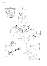
Page 24: ...24 A44 P DWG A44 P 01...

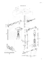
Page 25: ...25 A44 P DWG A44 P 02...

Page 26: ...26 A44 P SCHEMES B Pneumatic Scheme...

Page 27: ...27 A44 P...

Page 28: ...28 A44 P SCHEME C Plates location...

Page 29: ...available only on customer s request for specific order quantities to be confirmed SW Suitable for soft wood such as Cedar Pine Bass Banak Obeche Poplar Other materials Vertical Grain MDF MW Suitable...

Page 30: ...30 A44 P...

Page 31: ...31 A44 P...

Page 32: ......

Reviews: