14
A44-P
In case of continued use without needing to remove the frontal clamp from its position, it is possible to
fix it into the peg using the proper screw.
When shipping the machine it is advisable to lock down the frontal clamp by using the supplied knob.
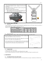
4.8.4 Fences adjustment
Machines are equipped with a fence composed by two separate parts.
Each part of the fence (right and left) is equipped with a knob that allows the tilting of supports.
The use of this fence is suggested for working frames with irregularities or little cambers on the external side.
If once the frontal clamping is inserted, the combining of the mitres is not perfect, the tilting fence can compensate such a fault.
For 90°(4 sided frames), 120°(6 sided frames) or 135° (8 sided frames) junctions, setting properly the two fence supports
(see fig. 18-19-20).
To modify the position of the two fence supports, proceed as follows:
• Remove the external screw by using the 5 mm Allen
wrench
• Release the internal screw and shift the fence up to reach
the holes located on the working bench
The exact position of fence supports can be obtained with the
help of a special fence.
Make sure that the 120° or 135° angle formed by the two
supports is exactly centered on the internal vertex of Wedges
claw head.
Picture 4.8.4.1
4.8.5 Protective shield adjustment
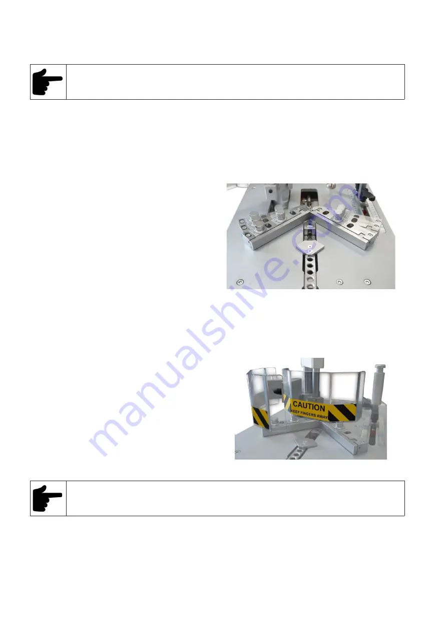
The machine is equipped with a protective shield (see pict. 4.8.5.1) made of transparent plastic material, to avoid the operator
accidental fingers crushing.
Proceed as follows to adjust the protection shield:
• position the mouldings to be assembled on the working
bench
• loosen the screw shaped handle fixing the protection
and lift or lower it at an height of about 6-8 mm from
mouldings to be assembled;
• tighten the screw shaped handle to lock the protection
shield.
Picture 4.8.5.1
The protection shield opening, effected by its overturning, causes the control pedal deactivation.
Even if the protective shield is properly adjusted, it is necessary following instructions listed below:
• Keep the fingers away from the frontal and vertical clamp working area.
• Disconnect the pressure supply during any maintenance intervention.
• Keep your foot off of the pedal while adjusting the machine.
4.8.6 Working pressure adjustment
The working pressure must be adjusted to the hardness of the mouldings to be assembled.
Summary of Contents for A44-P
Page 3: ...3 A44 P...
Page 21: ...21 A44 P...
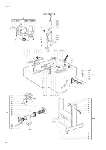
Page 24: ...24 A44 P DWG A44 P 01...
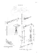
Page 25: ...25 A44 P DWG A44 P 02...
Page 26: ...26 A44 P SCHEMES B Pneumatic Scheme...
Page 27: ...27 A44 P...
Page 28: ...28 A44 P SCHEME C Plates location...
Page 30: ...30 A44 P...
Page 31: ...31 A44 P...
Page 32: ......


