17
A44-P
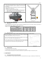
When working with big sized frames, on the machine can be mounted
a working bench extension (metal or wooden), and it can work in
tilted position.
Usually, when the machine is tilted back, the operator working position
is opposite to the normal one.
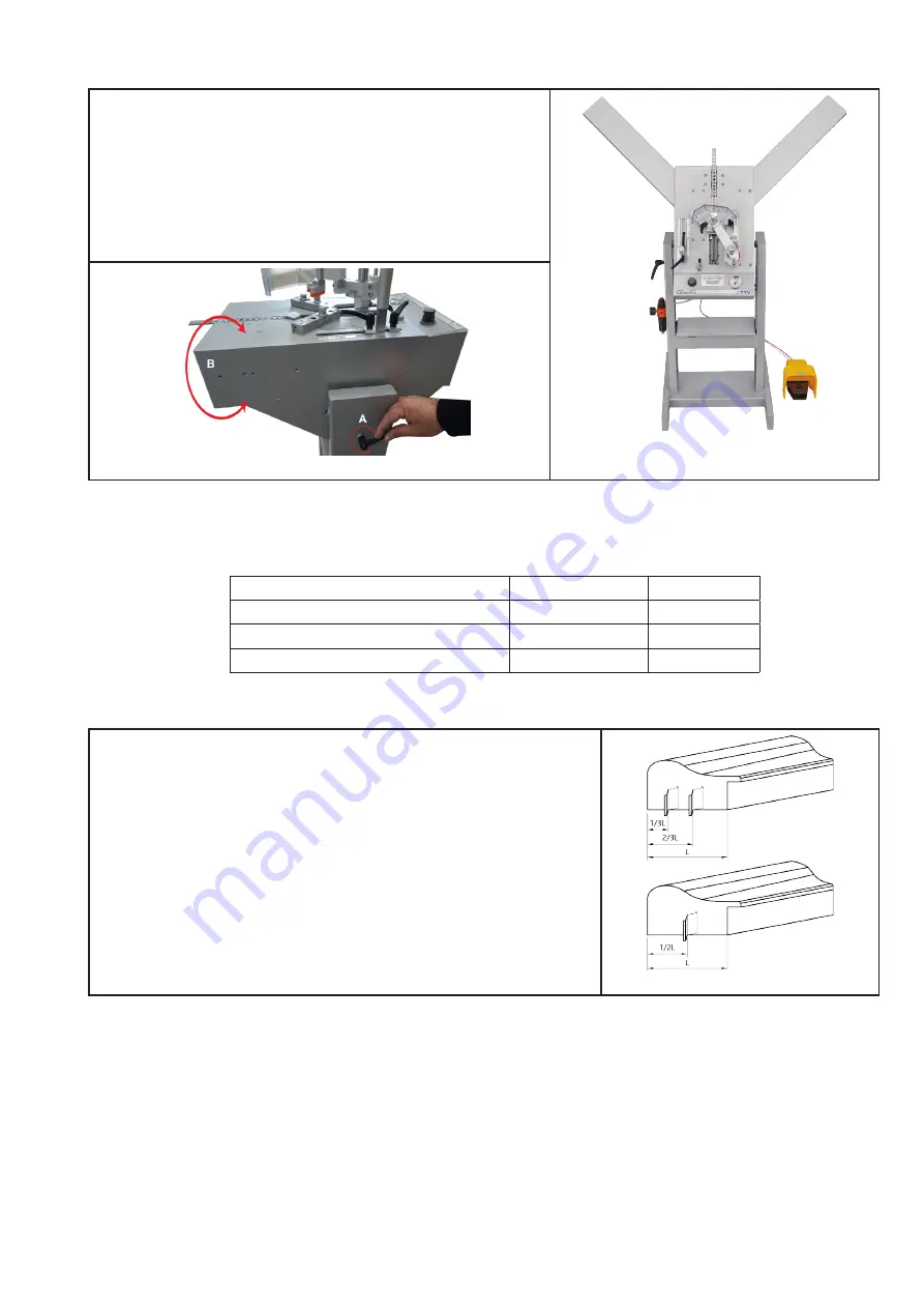
To tilt back the machine, operate as follows:
• loosen the handle located on floor stand right side (pict. 5.2.1-A)
• tilt the machine up to reach the desired angle (pict. 5.2.1-B)
• tighten the handle to lock the machine in position.
Picture 5.2.2
A44-P in tilted position with metal extension arms
Picture 5.2.1
5.3 TIPS FOR QUALITY JUNCTIONS
a)
Wedge types
In order to allow the machine to make excellent quality joints using different materials, it has been necessary to manufacture
different Wedges types for different uses (see attachment D).
Wedges can be classified in three different groups:
Material
Suggested code
Color Ref.
soft materials (wood, soft plastic)
SW
Green
for medium materials (wood, ...)
MW
Gray
for hard materials (wood, MDF, HDF)
HW
Red
b)
Assembling positions
It is advisable to operate as follows in order to achieve the best results in terms of junction quality:
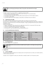
• Never drive Wedges near the external vertex. The minimum recommended
distance from the external vertex is at least 10 mm.
• When you want to make the junction using only one Wedge, the most suitable
position is in the middle of the moulding (see fig. 21)
• In case you want to insert 2 or more Wedges into each junction, we recommend
you to insert the most external one 1/3 from the external vertex and the most
internal one 1/4 from the internal vertex (not less than 5mm).
picture 5.3.1
5.4 MACHINE STOP
To stop it, lift your foot from the pedal.
It is possible also to disconnect the quick connect fitting from the air supply.
In case on long inactivity periods it is necessary to disconnect the quick connect fitting from pneumatic system.
6. MAINTENANCE
6.1 RECOMMENDATIONS FOR MAINTENANCE
Carry out maintenance or repair operations with the machine isolated from air supply, as indicated by the Manufacturer.
Summary of Contents for A44-P
Page 3: ...3 A44 P...
Page 21: ...21 A44 P...
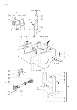
Page 24: ...24 A44 P DWG A44 P 01...
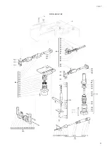
Page 25: ...25 A44 P DWG A44 P 02...
Page 26: ...26 A44 P SCHEMES B Pneumatic Scheme...
Page 27: ...27 A44 P...
Page 28: ...28 A44 P SCHEME C Plates location...
Page 30: ...30 A44 P...
Page 31: ...31 A44 P...
Page 32: ......


