background image

18

AV500HD

English

Video Output Setup

Use ↑↓ to place cursor to Video Output Setup button, system will reboot each time a resolution change is executed. Press 
Enter to sub-menu selection.

Use ←→ to select sub-menu options.
The default system settings are: 

  AUX 1 Resolution: 1080

  AUX 1 Source: PGM

  AUX 2 Resolution: 1080

  AUX 2 Source: PVW

  Frame Rate (PGM): 60P

  Video System: NTSC

AUX 1 Output Resolution Selection

AUX Source Selection

AUX 1 and AUX 2 Output Resolution Selection:
(PAL)

  1080

  720

  480 (576)

AUX 1 and AUX 2 Source Selection
-PVW
-PGM
-CH 1 - CH 5

Summary of Contents for AV500HD

Page 1: ...User s Manual Multi Format Video Switcher AV500HD...

Page 2: ...n the apparatus has been damaged in any way such as power supply cord or plug is damaged liquid has been spilled or objects have fallen into the apparatus has been exposed to rain or moisture does not...

Page 3: ...g should be one that is within easy reach and readily accessible Placement This device may interfere with radio and television reception Do not use this device in the vicinity of such receivers Noise...

Page 4: ...liders or other controls and when using its jacks and connectors Rough handling can lead to malfunctions When disconnecting all cables grasp the connector itself never pull on the cable This way you w...

Page 5: ...ut Ports 9 Monitor Select 10 Setup Menu Operations 13 Main Controls 13 Main Menu 13 Asystems Virtual Webcam Emulation Setup Guide 35 Asystems Direct Streaming Setup Guide 37 Specifications 40 Preset M...

Page 6: ...800HD s built in Multiview screen can output up to 5 images from different sources to a single high resolution display eliminating the need for multiple HD source and preview monitors For added creati...

Page 7: ...duct please carefully inspect the included items in the unlikely event of any missing or damaged items please contact your authorized retailer distributor for replacements AV500HD AV500HD Owner s Manu...

Page 8: ...e metal portions of other objects such as projectors This is due to an infinitesimal electrical charge which is absolutely harmless However if you are concerned about this connect the ground terminal...

Page 9: ...ys audio mixer channel EQs levels 2 SD Card Slot Still image input for DSK and Output Fade also use for firmware upgrade 3 Memory Section Buttons 1 to 4 Select or save to memory location 4 Joystick Co...

Page 10: ...el 12 Headphone Out 6 3mm Stereo x1 13 Channel Faders Main channel 1 12 KEY SEL Select Button Toggle KEY mod on and off Level Knob Adjust KEY background transparency level 14 Gain Knobs Input gain adj...

Page 11: ...PGM or CH 1 to 5 Note The internal audio signal is set to AUX 1 unless PGM is set to AUX 2 only else the audio signal remains in AUX 1 If AUX 1 and AUX 2 both set to PGM AUX 1 takes priority and the a...

Page 12: ...b to adjust PGM Out screen size 4 Double tap on PGM Out screen area to close PGM Out Note PGM Out and PVW Out will share the same positon and size data when PGM Out or PVW Out is closed the last posit...

Page 13: ...button icon 1 to 5 to switch channel 2a or using SEL knob to scroll through 1 to 5 Blue frame will appear as the knob scroll blue frame will disappear after 5 seconds of no action Fig 2c 2 CH 4 Selec...

Page 14: ...put Source Selects 1 AV Original audio source from HDMI SDI 2 Line External audio source 3 Tab directly to screen to select audio source for each channel selected button will change to blue b AUX Outp...

Page 15: ...to open Main Menu 2 Press MENU again or ESC to close Main Menu 3 Use buttons to navigate through Main Menu selection 4 Press buttons to navigate through sub menu selection PVW PGM CH3 CH3 CH2 CH1 CH4...

Page 16: ...n Corresponding Button Channel to Channel Source Selection Available Selections Digital HDMI In 1 4 HDMI Input source 1 through 4 SDI IN 2 4 DSK Contents of this channel will be displayed when DSK is...

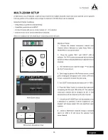
Page 17: ...until INPUT LED is selected The PVW screen and selected source channel borders are Blue indicating Multi Zoom adjustment is in progress 3 The selected source channel image will be placed into the Pre...

Page 18: ...16 AV500HD English Multi Zoom Area Selected Select a New Zoom Area Cross Point Channel assigned to Multi Zoom PVW PGM PVW CH1 CH1 CH2 CH3 CH4 CH2 CH4 CH5 CH5 CH5 PVW...

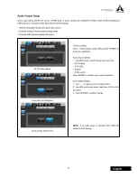
Page 19: ...ital USB audio AV IN Setup Menu Audio Source Selection Audio Delay Adjustment Cursor Location Use to select Audio Output Setup press ENTER to sub menu selections Audio Source Select 1 Use SEL knob to...

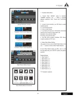
Page 20: ...b menu selection Use to select sub menu options The default system settings are AUX 1 Resolution 1080 AUX 1 Source PGM AUX 2 Resolution 1080 AUX 2 Source PVW Frame Rate PGM 60P Video System NTSC AUX 1...

Page 21: ...19 AV500HD English NTSC Frame Rate Select PAL Frame Rate Select Video System Select Frame Rate Selection Selection only applies to PGM PAL 60P 50P 30P 25P 30i 25i Video System NTSC PAL...

Page 22: ...the Effect Setup Menu you can edit the following settings Menu Selection Transition Setup PIP Setup Key Setup DSK Setup Output Fade Setup Transition Setup The 8 wipe pattern buttons which are used as...

Page 23: ...e 0 999 frames Time Frame 0 9 seconds 0 30 frames max frame interval will be limited by output frame rate 30 frames 30 and 60 Hz NTSC 25 frames 25 and 50 Hz PAL Use SEL knob to adjust clockwise CW fra...

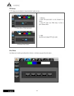
Page 24: ...an be called up by Setup Menu selection or directly by top panel Key SEL button PIP Setup Menu Width Adjustment PIP Border Color Select 1 Selection Width PIP border width 0 2 lines Default 0 no border...

Page 25: ...Default Green Custom color can only be changed when Key SEL button is enabled by using the eyedropper function Press ENTER to confirm selection 3 Key Filter Range Adjustment Use SEL knob to adjust ra...

Page 26: ...e image files will be shown in bottom menu and image can be previewed in the lower left window Use the select knob to scroll through the file list and use ENTER to confirm selection DSK Setup DSK chan...

Page 27: ...0 joining edge sharpness 6 EXT KEY When enabled the EXT KEY button will become solid EXT KEY will share the same settings with SOURCE and same input selection DSK and EXT KEY cannot be the same sourc...

Page 28: ...the type of fade out screen of the output Lower left corner displays the current output fade image use SEL to make selection and adjustment Output Fade Format Select 1 Format Solid Screen Solid Screen...

Page 29: ...justment 2 Solid Screen Color Black white red green and blue 3 SD jpg and bmp files located in SD card can be used The selection method is same as DSK 4 Internal Storage Captured image From Freeze fun...

Page 30: ...ntrol communication port Invert Y Axis Camera tilt control COM 2 RS232 remote control protocol port Camera COM 1 Setup 1 Please wait 30 seconds for the system to recognize the converter before any set...

Page 31: ...5 Stop Bit Selection 1 Default 2 6 Flow Control Selection None Default Xon Xoff Hardware To invert joystick s Y Axis direction Default at NORMAL Use SEL knob to make selection Normal UP UP DOWN DOWN...

Page 32: ...storage and video streaming 1 Internal Storage 5 GB reserve space INT is the root directory for internal storage Press ENTER to enter file management use to go to Next or Previous page When available...

Page 33: ...the audio output Mute Active 1 Press ENTER and use the SEL Knob to turn HDCP On and Off When HDCP is not turned on HDCP encrypted video sources will not be allowed to pass through PGM NOTE1 During str...

Page 34: ...Screen Editing Channel Label System Status The System Status menu gives a you glance of the entire system setup of your AV500HD This is a where you ll have a complete system setup information right on...

Page 35: ...l Selection All Reset all data to original factory default Preset Reset preset memory only Key Reset current Key Setup Menu only DSK Reset current DSK Setup Menu only Channel Setup Reset current Chann...

Page 36: ...data will be saved while performing FW upgrade OFF All data will be erased while performing FW upgrade Firmware Upgrade Place FW data in the SD card If FW data exists in the SD card it will be displa...

Page 37: ...hin the Private network settings while leaving the Public network settings turned on Turn off your antivirus software for installation to prevent installation being blocked Alternatively you can add t...

Page 38: ...whether you would like to the NETCAM IP address Click Yes and you will be prompted to enter the IP address that is assigned to your AV500HD in the System Status menu Enter the IP address into the box...

Page 39: ...protocol is used for establishing and controlling media sessions between end points Please refer to the following steps to begin webcam emulation setup procedures For video streaming platform Asystems...

Page 40: ...io scroll down and check the Use custom audio device box and select ASYSTEMS Network Camera Audio Capture as your audio source and click OK to exit the window 4 Click Settings in the lower right hand...

Page 41: ...eam Key in the respective boxes and click OK to exit 6 On the main screen click Start Streaming to begin streaming your video content Please note that depending on the type of streaming platform you u...

Page 42: ...REMOTE CONTROL 1 COM DB 9 RS232 For remote control program access x1 EXTERNAL STORAGE 1 SD Card Standard SDHC slot For still image input and firmware upgrade x1 TALLY LIGHT 1 Tally 1 DA 15 CH1 to 5 PV...

Page 43: ...lo CH5 6 11 12 Level PEQ Mute Main Delay Main Level Mono Reverb Send Reverb Level AUX Send AUX Delay Solo 2 Level Control 100mm fader 3 Level Meter 2 x 6 segment Electrical 1 Audio Format SDI Linear P...

Page 44: ...frame sec Time 1 00 Frame 030 Time Frame 1 00 II Wipe Pattern 1 Position Button 1 to 8 8 III PIP 1 Position Button 1 to 4 1 2 Size Position Last adjusted PIP size and position Button 1 size and posi...

Page 45: ...2 Frame Rate P30 and P60 P30 Audio Source Default USB and Analog Default Audio Delay 0 00 to 9 99 seconds 0 00 3 3 Frame Rate P30 and P60 P30 Audio Source Default USB and Analog Default Audio Delay 0...

Page 46: ...B PIP Setup 1 Width 0 to 2 0 2 Color White Black Red Blue and Green Red C Key Setup 1 Filter Green Blue Black White and Custom Green 2 Filter Range 0 to100 25 3 Edge Sharpness 0 to 100 0 4 Width 0 to...

Page 47: ...45 AV500HD English IV System Status A Input Labeling 1 CH1 Input Text Blank 2 CH2 Input Text Blank 3 CH3 Input Text Blank 4 CH4 Input Text Blank 5 CH5 Input Text Blank...

Page 48: ...www asystems sys com...

Reviews: