4
DMA8825 / DMA8813 / DMA8425 / DMA8413
English
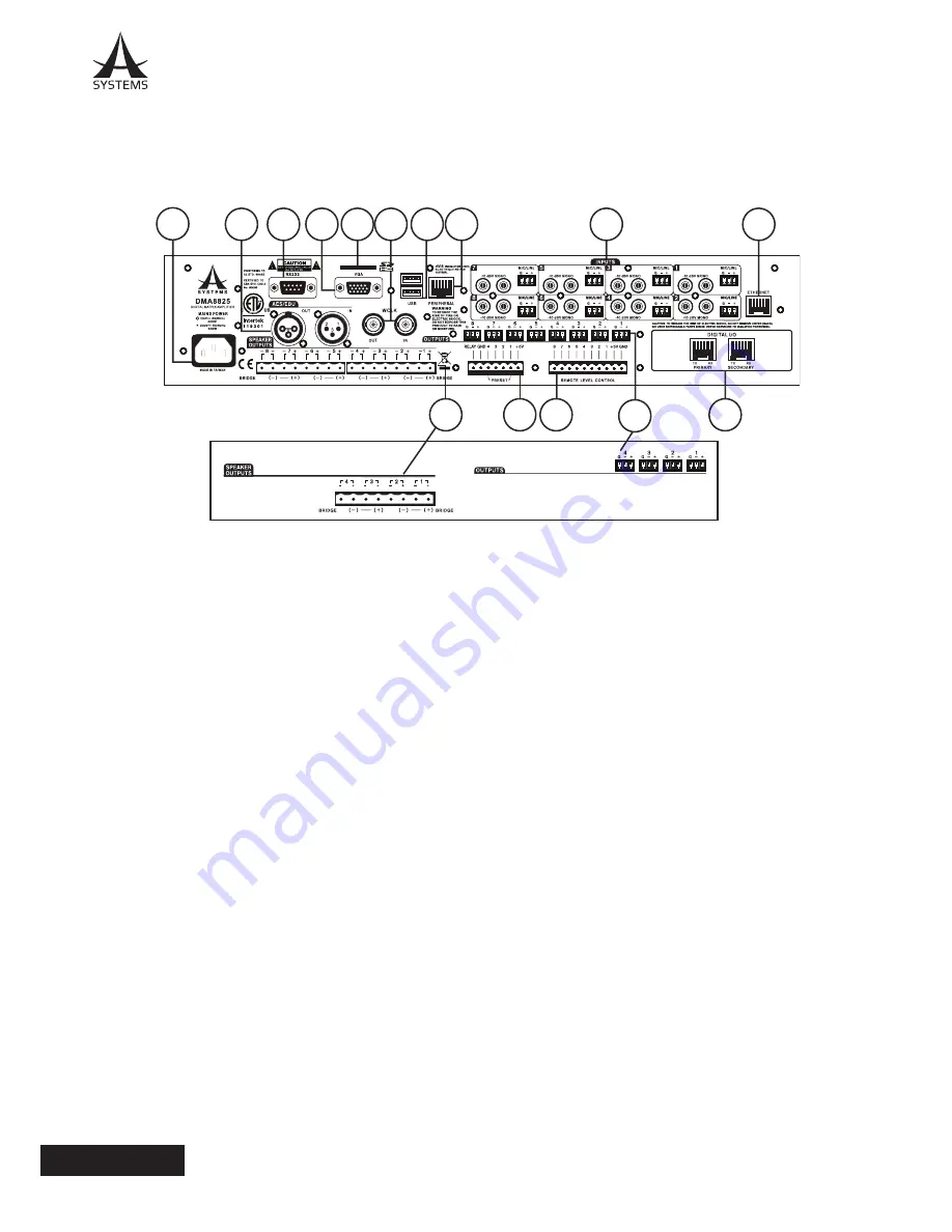
REAR PANEL
1. AC Power Connector
This power inlet is for connecting a standard IEC
power cable. Under no circumstances should the user
remove the grounding pin on the power cable.
2. AES/EBU Connector
For connecting AES/EBU-enabled devices.
3. RS-232 Connector
For remote control through non-Ethernet based hardware
that utilizes a RS-232 control data protocol. This feature
is only found on the DMA8825� A detailed protocol
document can be found on the Asystems website.
4. VGA Connector
Connect this port to an appropriate video screen to view
the DMA’s internal software. This can be controlled by
any connected wired or wireless mouse�
5. SD Card Slot
Insert an SD card here to play digital audio files.
6. WCLK Connector
This port is for connection of a master clock,
enabling multiple digital audio devices to be perfectly
synchronized.
7. USB Ports
These USB ports are for connection of a standard
wired or wireless USB mouse for stand-alone control
of the internal software. The second USB port can be
used when performing firmware updates.
8. SPEAKER OUTPUTS (Amplified Output)
For connecting passive loudspeakers.
9. PERIPHERAL Connector
For connecting the Asystems RM-6E programmable
remote control (sold separately).
10. PRESET RECALL Connector
For connecting Asystems’ RM-4 series remote preset
recall control (sold separately).
11. REMOTE LEVEL CONTROL Connector
For connecting Asystems’ RM-2VR series remote
level control (sold separately).
12. INPUT Connectors
Two types of input connectors are offered - Euroblock
and unbalanced RCA.
13. OUTPUT Connectors
DMA matrix amplifiers adopt 3-pin Euroblock output
connectors for line-level output. These can be used
as balanced or unbalanced connections (see section
“Audio Output” on page 6 for more).
14. DIGITAL I/O Expansion Card Slot
This slot is for installing Asystems’ DT44 or DT88
Dante Networking card to enable the DMA as a
networking portal to other Dante-enabled devices.
15. ETHERNET Connector
RJ-45 connector for connecting the DMA8825,
DMA8813, DMA8425 or DMA8413 to a PC or local
area network.
The Asystems
DMA8825
,
DMA8813
,
DMA8425
and
DMA8413
share the same basic I/O design and layout. The major
difference is that the
DMA8825
and
DMA8813
have
8
speaker output connectors and
8
line-out connectors, while the
DMA8425
and
DMA8413
have
4
speaker output connectors and
4
line-out connectors (as shown below).
15
14
13
11
8
12
7
6
3
5
4
2
1
9
10
DMA8425 / DMA8413
DMA8425 / DMA8413
Summary of Contents for DMA8825
Page 1: ...User s Manual Manual del Usuario Digital Matrix Amplifiers DMA8825 DMA88 1 3 DMA8425 DMA84 1 3...
Page 22: ......
Page 41: ......
Page 42: ...www asystems sys com...


