background image

Page 24 06/2021

Installation and Operating Instructions 
UPS Edition One 6kVA, 10kVA

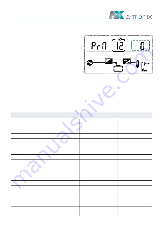
4.3.12 Parallel redundancy quantity setting

Parallel redundancy quantity setting

(

NOTE:

 Inside the broken-line  

is the flashing part)

If you press the DOWN key under the parallel 
quantity setting, you will get to the parallel 
redundancy quantity setting. You can set the 
parallel redundancy quantity as follows:

■ 

  Press ENTER/ON to enter the value setting status.  

Press UP & DOWN to set the parallel redundancy amount and press ENTER/ON to confirm. 
The range for the parallel redundancy quantity is 0~1.

■ 

  Press UP& DOWN to go to the parallel quantity setting or exit the mode setting.  

Then the setting of the UPS LCD control panel is performed.

4.4 Alarm Information


Item  USV Alarm Warning 

Buzz 

LED

Rectifier Fault 

Beep continuously 

Fault LED lit

Inverter fault (Including  


Inverter bridge is shorted) 

Beep continuously 

Fault LED lit

Inverter Thyristor short 

Beep continuously 

Fault LED lit

Inverter Thyristor broken 

Beep continuously 

Fault LED lit

Bypass Thyristor short 

Beep continuously 

Fault LED lit

Bypass Thyristor broken 

Beep continuously 

Fault LED lit

Fuse broken 

Beep continuously 

Fault LED lit

Parallel relay fault 

Beep continuously 

Fault LED lit

Fan fault 

Beep continuously 

Fault LED lit

10 

Reserve 

Beep continuously 

Fault LED lit

11 

Auxiliary power fault 

Beep continuously 

Fault LED lit

12 

Initialization fault 

Beep continuously 

Fault LED lit

13 

P-Battery Charger fault 

Beep continuously 

Fault LED lit

14 

N-Battery Charger fault 

Beep continuously 

Fault LED lit

15 

DC Bus over voltage 

Beep continuously 

Fault LED lit

16 

DC Bus below voltage 

Beep continuously 

Fault LED lit

17 

DC bus unbalance 

Beep continuously 

Fault LED lit

18 

Soft start failed 

Beep continuously 

Fault LED lit

Summary of Contents for 9885107

Page 1: ...ty VA Article number a TroniX UPS Edition One 6kVA 6000 9885107 a TroniX UPS Edition One 10kVA 10000 9885108 06 2021 Seite 1 ONLINE UPS Installation and Operating Instructions a TroniX UPS Edition One...

Page 2: ...evel With the a Tronix Series Edition One your installations are safely protected from power supply problems and the functionality of your equipment is maintained Read carefully before use Read this m...

Page 3: ...nd turn off UPS 13 4 1 1 Start up operation 13 4 1 2 Turn off operation 13 4 2 Faceplate display 14 4 2 1 Faceplate display illumination 14 4 2 2 LCD display 15 4 3 Parameter settings 17 4 3 1 Mode se...

Page 4: ...sign to supply electrical devices 230 V AC which in total do not exceed the rated power Any other use or use beyond this is considered improper and may result in personal injury property damage and or...

Page 5: ...Batteries must never be brought into contact with heat sources or flames Do not attempt to dispose of the batteries by burning them Defective accumulators must be disposed of in an environmentally fri...

Page 6: ...Warnings and notes are indicated by the corresponding symbols pictograms and must be observed WARNING Warning of dangerous electrical voltage General warning of danger points Warning when handling ac...

Page 7: ...2 Product Introduction 2 1 Product view UPS 6 10kVA 6 10kVA Front Panel view 6 10kVA Rear Panel view without maintenance 1 USB to connect the UPS to a PC 2 EPO for emergency shutdown 3 Parallel port...

Page 8: ...ne 6kVA 10kVA 6 10kVA Rear Panel view with maintenance 1 USB to connect the UPS to a PC 2 EPO for emergency shutdown 3 Parallel port 1 4 Parallel port 2 5 Intelligent slot 6 RS232 7 Input switch 8 Ter...

Page 9: ...t UPS Principle Diagram 1 Mains input 2 Rectifier 3 Inverter 4 Bypass switch 5 Bypass 6 Charger 7 Battery bank 8 Extended Battery Pack optional 9 UPS output 2 3 Product Category USV Type Remark Standa...

Page 10: ...lations All environmental and operating conditions requirements specified in the technical data must be complied with in order to ensure the correct functioning of the UPS The unit may only be set up...

Page 11: ...responding input and output terminals The protective earth conductor refers to the cable connection between the parts that consume electrical current and the earth cable The cable diameter of the eart...

Page 12: ...e event of a supply emergency the software ensures that all data is saved and the units are shut down properly Communication port SNMP Optional Optionally the UPS can be equipped with an SNMP communic...

Page 13: ...LCD display The LED display of the UPS shows the current status of the UPS 4 1 2 Turn off operation 1 Turn off the UPS in line mode without batteries a Press and hold the ESC OFF button for 2 seconds...

Page 14: ...10kVA 4 2 Faceplate display 4 2 1 Faceplate display illumination Overview of the operating panel of the UPS 1 INVERTER LED 2 BATTERY LED 3 BYPASS LED 4 ALARM LED 5 LCD display 6 UP button 7 DOWN butt...

Page 15: ...uency 02 Output Voltage Frequency 03 Bat Voltage Current pos 04 Bat Voltage Current neg 05 Temp Ambient temperature 06 Load Load 07 Bus voltage Bus voltage 08 UEA Version of software 09 Model Model Wh...

Page 16: ...ns UPS Edition One 6kVA 10kVA 2 Press the DOWN button and the UPS goes to the next page each time as shown below 2 Input voltage 3 Output voltage 4 Bat voltage positive 5 Bat voltage negative 6 Load 7...

Page 17: ...setting parameter Press Enter On to enter the value setting status press the UP or DOWN key to set the value Press the ON key to confirm Press and hold the DOWN key until the setting parameter is exit...

Page 18: ...mode setting or the frequency setting NOTE When powered by inverter it is necessary to turn off the inverter before setting voltage and frequency level 4 3 3 Output frequency setting Frequency settin...

Page 19: ...sing UP or DOWN for a long time the battery capacity can be quickly reduced Use the UP DOWN keys to go to the frequency setting or to set the battery quantity 4 3 5 Battery quantity setting Battery qu...

Page 20: ...ltage upper limit is 5 10 15 or 25 25 only for 220V output Use the UP DOWN key to access the battery quantity setting or to set the lower limit of the bypass voltage 4 3 7 Bypass Volt Lo setting Bypas...

Page 21: ...he selection includes ON and OFF NOTE ON mute OFF no mute Press the UP or DOWN button to stop muting and save the muting status and to switch to the lower bypass voltage limit setting or the battery s...

Page 22: ...itch to battery mode every 30 days The battery self test time is 10 seconds If you select ON2 the UPS can automatically switch to battery mode every 30 days The battery self test time is 10 minutes If...

Page 23: ...the UP DOWN buttons takes you to the battery self test setting or parallel quantity setting NOTE No parallel cable can be connected when setting the parallel parameters 4 3 11 Parallel quantity settin...

Page 24: ...ep continuously Fault LED lit 2 Inverter fault Including Inverter bridge is shorted Beep continuously Fault LED lit 3 Inverter Thyristor short Beep continuously Fault LED lit 4 Inverter Thyristor brok...

Page 25: ...LED blinking 32 Overload Once per second INV or BPS blinking 33 No battery Once per second BATTERY blinking 34 Battery under voltage Once per second BATTERY blinking 35 Battery low prewarning Once pe...

Page 26: ...attery is completely discharged until the under voltage protection switches off It has to be fully recharged immediately 2 In areas with high temperatures the batteries should be manually charged and...

Page 27: ...disconnected Contact your supplier Mains normal but UPS has no input UPS input breaker open circuit Press the breaker for reset Short back up time Battery not fully charged Keep UPS connecting with m...

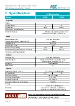
Page 28: ...20 x 9 20 x 9 Charging current max Default 1 Output Voltage V AC 208 220 230 240 Frequency Hz Mains mode 10 of nominal voltage Battery mode 50 60 0 1 Hz Waveform Pure Sinewave Crest factor 3 1 Others...

Reviews: