50
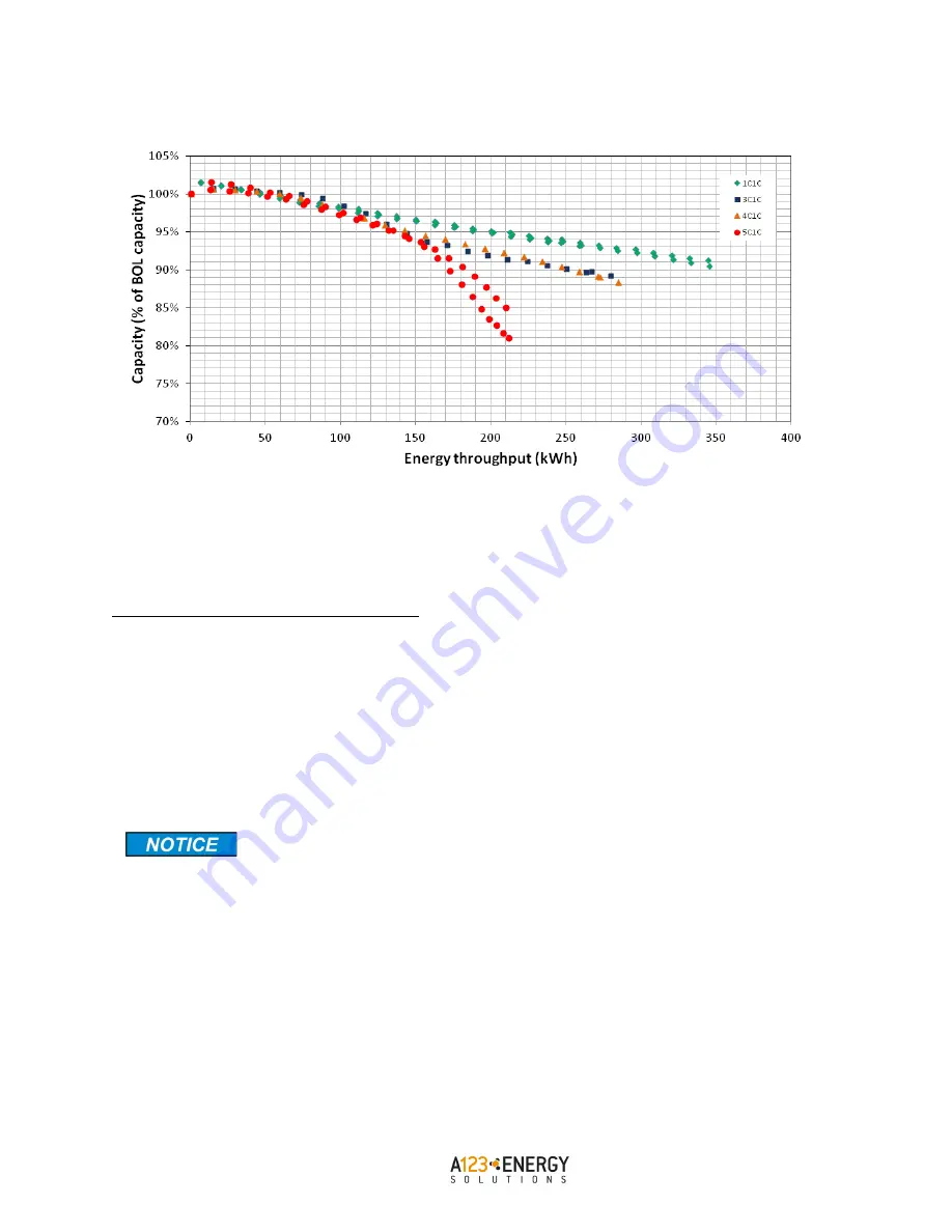
Figure 26 – AMP20 cell* capacity degradation vs. time for various recharge rates**
* Refer to Appendix A for data on other A123 cells.
** Refer to Appendix A for the recommended fast-charge current limits of A123 cells.
Recommended Float Charge Method for Strings
To hold the voltage of the cell string at the end of charge voltage (after reaching 100% SOC) for prolonged periods
of time, lower the end of charge voltage to the recommended float-charge voltage. Determine the recommended
float voltage by multiplying the number of series cells or elements in the string by the recommended float-charge
voltage of a single cell.
Eq 7.
Number of cells in series x Recommended Float Charge Voltage / cell = Float Charge Voltage / string
Refer to the Appendix A for recommended float charge voltage.
Even if at the start of the extended float mode, all the cells are balanced, the BMS must
monitor all the cell voltages throughout the float mode period. If one of the cells has a
higher self-discharge rate than the others, its terminal voltage will fall with respect to
the others, and the other cell voltages may rise past the upper cell voltage limits.
Therefore it is important that the charge current shall be limited whenever any cell in
the string reaches its maximum recommended float voltage.
Discharging Current Limits
In order to safely operate the cells, the current discharging from the cells must be kept below the point at which it
generates too much heat inside the cell. Too much heat can cause excessive temperatures which can lead to
accelerated capacity loss over time. Temperatures beyond the absolute maximum allowable cell temperature can
cause immediate damage to the cell. In general any skin temperature above 35 °C will cause accelerated capacity
Effect of charge rates for 100% DOD cycling at 23 °C for AMP20 cell


