www.a2asimulations.com
ACCU-SIM V35B BONANZA
:::
A2A
SIMULATIONS
15
FOR SIMULATION USE ONLY
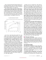
1. When the yoke is pushed
forward to lower the nose, the
ruddervators move downward
as does a conventional elevator
control surface. However, they
also necessarily create additional
forces which push and pull to
each side (yaw axis) as well.
Each ruddervator offsets the
other’s yaw force, but because
of the dual direction of forces
created by ruddevators, they are
functionally less aerodynami-
cally efficient than a similarly
sized and displaced horizon-
tal control surface. Accordingly,
rudddervators must be larger
and/or be displaced farther than
a conventional horizontal ele-
vator surface to create an equal
force in the pitch axis.
2. When the yoke is pulled
rearward to raise the nose, the
ruddervators move upward as
does a conventional elevator control surface. However, they
also create additional forces which push and pull to each
side as well, as described above. The inefficiency caused
by the offset forces is similar to when the ruddervators are
pushed downward.
3. When the right rudder pedal is pushed to yaw the nose
to the right the ruddevators both move to the right. In order
for the left ruddervator to move to the right it must also
move upward creating an additional nose up force, and
when the right ruddervator moves to the right it must also
move downward creating an additional downward pitch
force. The ruddervators’ up and down pitch forces cancel
each other out so that only a right yawing force is created.
The canceled- out upward and downward forces create inef-
ficiency as stated above.
4. When the left rudder pedal is pushed to yaw the nose
to the left, the ruddevators both move to the left. In order
for the left ruddervator to move to the left it must also move
downward creating an additional nose down force, and
when the right ruddervator moves to the left it must also
move upward creating an additional nose up force. Each of
the ruddervators’ up and downward pitch forces cancel each
other out so that only a left yawing force is created. The
canceled- out upward and downward forces create ineffi-
ciency as stated above.
5. When both the yoke and either rudder pedal are moved a
combination of the above control surface movements is cre-
ated so that the nose may be raised or lowered while simul-
taneously yawing the nose to the left or right as desired.
As you may imagine, the linkages required to move the
ruddervators to comply with the exact forces which a pilot
may require are quite complicated.
On a “V”- tail Bonanza, with full up elevator and with no
rudder input, the left rudderva-
tor is displaced 22½º upward.
With full right rudder and with
the elevator neutral, the left
ruddervator is displaced 23º
upward, and with full up eleva-
tor and with right rudder simul-
taneously, the left ruddervator is
displaced 44º upward. By con-
trast, the elevator of the con-
ventional tail of an A36 Bonanza
is limited to 23º upward and 20º
downward displacement, while
the rudder is limited to 25º left
or right displacement.
“V”- TAIL DISADVANTAGES:
■
Weight
While Bonanza’s “V”- tail is leg-
endary, the myriad aeronautical
claims that Beech has perenni-
ally made for it do not entirely
or even partially live up to that
legend. Bonanza’s “V”-
tail is
not lighter than a conventional tail arrangement as the two
ruddervators must each be larger than any of the three con-
ventional tail surfaces. Because the control force of the two
ruddervators must equal the control force of the conven-
tional three- surface design, the two ruddervators, in sum,
must have approximately equal or greater area because of
“V”- tail’s aerodynamic inefficiencies when compared to a
conventional tail. Additionally, the complex control linkage
of the “V”- tail arrangement is heavier than the far simpler
conventional- tail linkage and is located at the most rear-
ward position. For example, a 1968 E33A Debonair, which is
virtually identical to a similarly equipped 1968 V35A “V”-
tail Bonanza except for the tail surfaces, is 45 lbs lighter
than V35A. However, this is not the total story of the disad-
vantages of the “V.”
■
Greater interference drag
NACA wind- tunnel studies of the generic “V”- tail design
have found that a small amount of interference drag is
reduced by the reduction of one intersection of tail surfaces
(two instead of three.) However, what small advantage may
be gained thereby is virtually eliminated by the increase of
interference drag created at the proximate inside surfaces of
the “V” surfaces where they are attached to the aft fuselage.
Interference drag caused by the proximity of the inside base
of each “V” surface occurs in this manner: Air molecules
moving past the lower inside surfaces of the ruddervators
become commingled and disorganized creating a disturbed
airflow which creates interference drag.
■
Greater induced drag
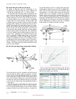
In order to ensure pitch stability, the aft pitch controlling
surfaces of any aeroplane must be set at such a positive
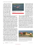
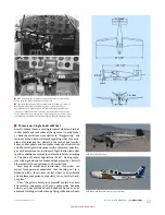
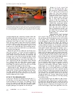
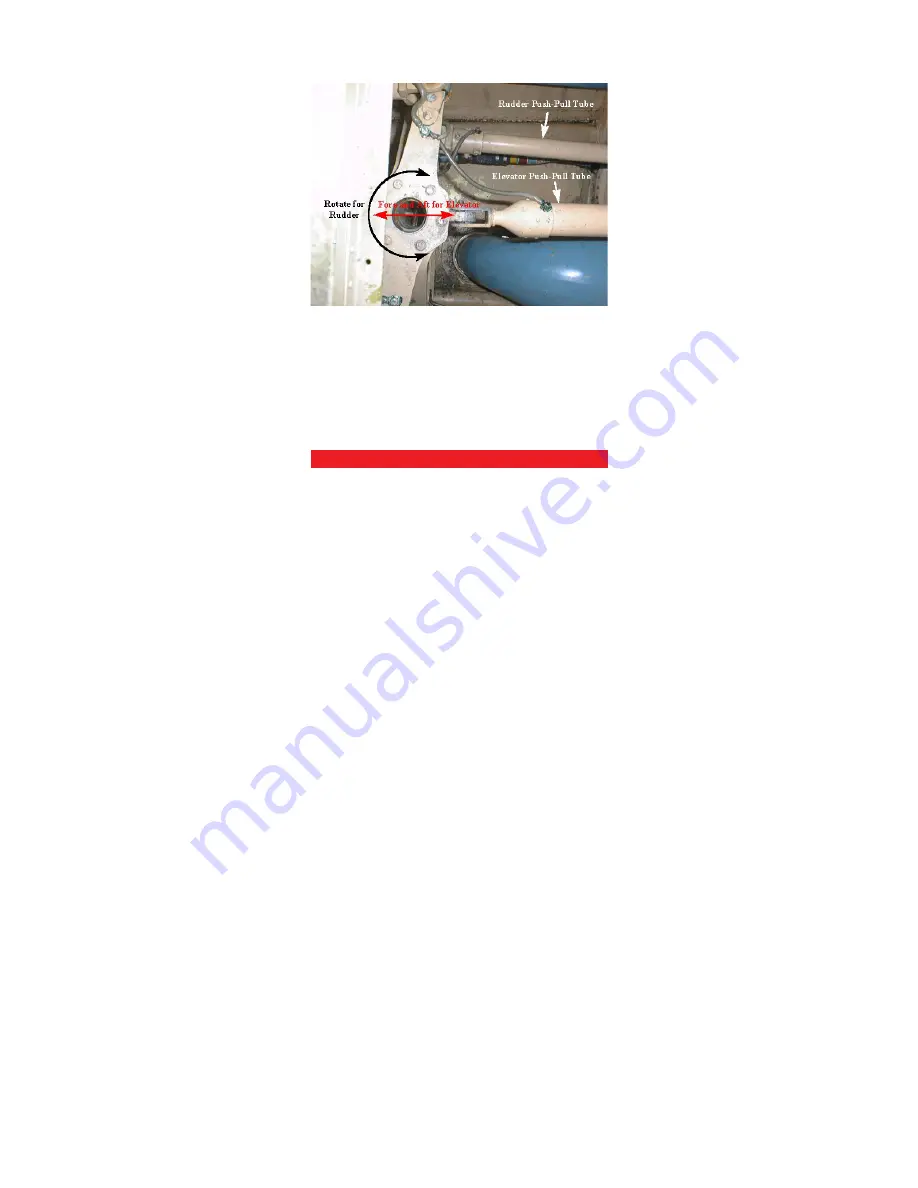
“V”- tail mixing linkage: The blue section shown is the fuselage’s
rearmost end looking up from underneath. There are two rods
extending off to the left of this photograph that connect to the
actual ruddervators. Rightward motion of the top rod (due to
either rightward motion of the entire mixer assembly due to a
pitch command, or clockwise rotation of the assembly due to
a yaw command) will deflect the ruddervator one direction;
leftward motion will deflect it the other direction. This is the same
for the other ruddervator similarly connected past the bottom of
the photograph. Simple, eh?
Summary of Contents for BONANZA ACCU-SIM V35B
Page 1: ...A2ASIMULATIONS BONANZA ACCU SIM V35B BONANZA ...
Page 3: ...A2ASIMULATIONS BONANZA ACCU SIM V35B BONANZA ...
Page 5: ...www a2asimulations com ACCU SIM V35B BONANZA A2ASIMULATIONS 5 FOR SIMULATION USE ONLY ...
Page 27: ...www a2asimulations com ACCU SIM V35B BONANZA A2ASIMULATIONS 27 FOR SIMULATION USE ONLY ...
Page 58: ......
Page 68: ...68 A2ASIMULATIONS ACCU SIM V35B BONANZA www a2asimulations com FOR SIMULATION USE ONLY ...
Page 112: ......


